


AD-1252 Thermal Dispersion Probe Airflow Measuring System Installation Instructions
16
Lock the fan speed, dampers, and set VAV boxes to
known positions while measurements are taken and
document all settings for future reference.
Complete the following steps to calculate the gain and
offset for the controller.
Measurements must be made
in feet per minute (FPM)
. The display can be changed
to (M/S) or CFM (L/S) when calibration is complete and
will not change mA output values. Only displayed
values change unless scaled output value is adjusted.
This does not change gain and offset calibration
settings.
1.
Set the in controller values for gain equals 1.0 and
offset equals ZERO, and set the controller to
display FPM. (FACTORY RESET sets Gain = 1,
Offset = 0, and velocity units to FPM.) If the units
displayed need to be for volume (CFM and L/S),
you can change the units that are displayed when
calibration is complete and make sure that the area
calculation is correct for the area where
measurements are being taken.
2.
Set the fan to a lower flow rate. (See the
introduction above to identify two expected flow
conditions.)
3.
Record the FPM displayed on the controller during
the time that reference measurements are being
taken and time-average for improved calibration
results.
4.
Record reference measurement FPM. Make sure
the units are FPM for all measurements.
5.
Set the fan to a higher flow rate. (See the
introduction above to identify two expected flow
conditions.)
6.
Record the FPM displayed on the controller during
the time that reference measurements are being
taken.
7.
Record the reference FPM. Make sure that the
units are FPM for all measurements. If the units are
for volume (CFM and L/S), make sure that the area
calculated is correct for each area where
measurements are being taken.
8.
Calculate the new gain for the controller.
9.
Calculate the offset for the controller.
10. Enter the gain and the offset for the controller.
Note:
If the offset is greater than the zero cutoff,
adjust the zero cutoff to a value greater than the offset
value to display zero during no flow conditions. The
Controller displays negative offset values when off but
will not output a negative voltage. If the units displayed
need to be for M/S or for volume (CFM and L/S), you
can change the units that are displayed when
calibration is complete, and make sure that the area
calculation is correct for the area where measurements
are being taken.
ZERO CUTOFF
This option submenu sets the zero velocity reference
point. Ensure that there is no airflow to the probe
sensors before accessing this submenu to set the zero
velocity reference point.
For firmware versions earlier than 8.5, the LCD screen
displays ARE YOU SURE. Use UP and DOWN to scroll
YES or NO. Press ENTER to accept the value.
Starting with firmware level 8.5, set the zero cutoff
value by pressing the UP (increase) or DOWN
(decrease) arrows.
The calculated velocity indicates zero when it reaches
the zero cutoff value.
Note:
The factory default is 40 FPM.
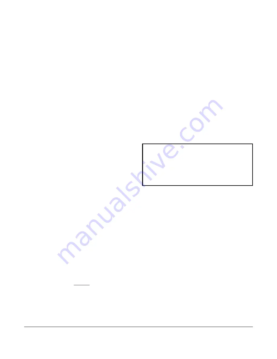
FI
G
:g
ai
n
A = Value calculated in Step 7.
B = Value calculated in Step 4.
C = Value calculated in Step 6.
D = Value calculated in Step 3.
Gain
(A - B)
(
D)
C -
=
Figure 22: Gain Value
IMPORTANT:
For firmware versions earlier than
version 8.5, use this function only when there is a
known velocity to the probe. If you use this function
when the probe sensors are measuring any airflow,
the system uses that airflow value as the zero
airflow velocity reference point and provides a zero
output (4 mA).
FI
G
:o
ff
set
B = Value calculated in Step 4.
E = Value calculated in Step 8.
D = Value calculated in Step 3.
Offset
(B - (E x D))
=
Figure 23: Offset Value


