background image

Mounting and Installation

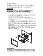
The diagram below shows a typical mounting procedure into a fiberglass panel. 

Always follow proper safety procedures. Wear eye-protection at all times with 
a dust mask and gloves when cutting.

 A mounting template is included to aid in 

measuring and marking the mounting surface before cutting or drilling. 

Before drilling or cutting, make sure there is adequate space behind the 
mounting surface to fit the MM100s, including its wire harness.

1. 

Press along the perforation to remove the center section of the mounting 
template. (Discard the center section.) The template can be used to verify 
there is sufficient flat surface area for mounting and as a guide for cutting the 
opening. Tape the template to the mounting location and mark the surface for 
cutting the opening and drilling pilot holes. 

2. 

Use a jigsaw or rotary tool to cut an opening in the mounting surface. If 
necessary, use a file or sandpaper to adjust the opening for proper fitment and 
smooth the edges.

3. 

Place the MM100s into the opening and check that the mounting holes remain 
aligned with the pilot hole marks taken from the template. If not, adjust and 
mark new holes as necessary.

4. 

Remove the MM100s and drill four (4) pilot holes in the mounting surface at the 
pilot hole marks.

5. 

Peel the adhesive backing from the mounting gasket and affix to the rear of the 
bezel. Connect all wiring and place the MM100s into the opening.

6. 

Secure the MM100s using the four (4) stainless steel screws. Press the trim ring 
onto the front of the MM100s.

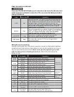
Power Connections


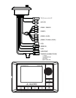
The 4-pin plug with wire leads is used to make power related connections. Make 
sure to carefully plan the wiring of your system prior to routing wires and making 
connections. Refer to the table on the next page when making power connections.

Summary of Contents for MediaMaster 100s

Page 1: ...dern vehicle systems we do not recommend self installation unless you have extensive experience in automotive and marine electrical systems Should you decide to install this product yourself please ta...

Page 2: ...installed systems If a dry environment is not available a location that is not exposed to heavy splashing may be used While this product is designed to be water resistant it should never be submerged...

Page 3: ...of the FCC Rules Operation is subject to the following two conditions 1 This device may not cause harmful interference and 2 this device must accept any interference received including interference t...

Page 4: ...and drilling pilot holes 2 Use a jigsaw or rotary tool to cut an opening in the mounting surface If necessary use a file or sandpaper to adjust the opening for proper fitment and smooth the edges 3 P...

Page 5: ...rs Wiring Harness Connections Harnesses exiting the rear of the unit are used to connect to aftermarket amplifiers equipment and media devices Depending on your specific equipment you may or may not u...

Page 6: ...0 0 UHFHLYHU RQO 17...
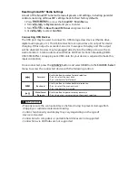
Page 7: ...s Press to access Zone 1 audio settings Press and hold to access the System Settings Main Menu Forward Use this button to make a forward selection Press to Tune in the next frequency AM FM WB or chann...

Page 8: ...Level Selectable output voltage 4V 2V 1V or Off Renames the zone to Subwoofer in the Audio Zone Levels menu and displays it after Zone 1 Level Control Mode Settings Start up Volume This setting adjust...

Page 9: ...ure your SiriusXM Connect Tuner is properly installed After you can hear the Preview channel tune to Channel 0 to find the Radio ID of your tuner In addition the Radio ID is located on the bottom of t...

Page 10: ...Press to access the SiriusXM Main Menu 2 Turn to scroll through menu options 3 Press to make selections Parental Controls Some SiriusXM channels contain mature content When the Parental Controls feat...

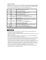
Page 11: ...Wire USB Port for Panel Mounting XMD USB 3 5MM PNL An appropriate USB cable for your device is required to make this input connection Once connected press the button and select USB from the SOURCE Sel...

Page 12: ...enu options Press to access the USB Main Menu options Press to go back or return to the Now Playing Screen Compatible models include iPhone 5 5c 5s 6 6s 6 and 6s equipped with Lightning connector Prop...

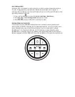
Page 13: ...Alert and press to enter 3 Turn to select ON or OFF and press to enter Optional Remote Controller Connecting an optional MMR 20 Wired Remote Controller sold separately will add auxiliary control func...

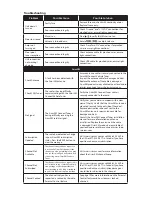
Page 14: ...ar view of the sky Verify that the SiriusXM antenna is mounted securely to the outside of the vessel Remove obstructions above of next to the SiriusXM antenna Inspect antenna cable for damage and kink...

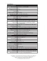
Page 15: ...o 1710 kHz 10 kHz step NOAA Weather Band Tuner 162 400 MHz to 162 550 MHz 0 025 MHz step Favorites 18 presets across all tuners Bluetooth Profile A2DP v1 2 AVRCP v1 4 Core Specification Version 2 1 ED...

Reviews: