3
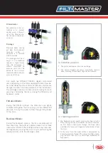
Filtered water
We recommend the ins-
tallation of a manual
control valve in the out-
let of the filtration sta-
tion to make maintenan-
ce easier.
Drainage
Drainage water coming
out from the backwash
hydraulic valves is
collected in a common
HDPE manifold.
The drainage must be at
height 0. If installation
requires a higher level,
then the difference in
meters translated to
pressure units must be
added to the minimum
recommended backwash
pressure (2,5 bar).
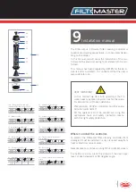
Our range has different filtration degree color-coded
discs depending on the total suspended solids of raw wa-
ter to be filtered and our automatic filtration stations are
designed to match flow requirements of the installation.
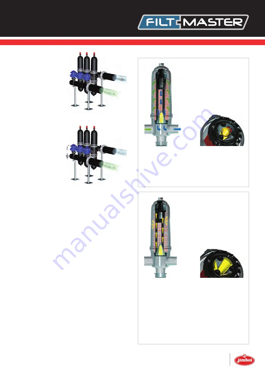
The cartridge spine has an internal piston spring for com-
pressing or releasing the discs during the filtration and
backwash cycles.
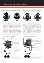
Filtration Mode:
During the filtration process the filter discs are tightly
compressed together by the spring and the differential
pressure, forcing the water to flow through the grooves
of the discs.
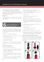
Backwash Mode:
During the backwash process, the discs are released. At
the same time, the multi-jet nozzles present in the three
internal manifolds of the cartridge spine sprays clean wa-
ter tangentially causing the discs to spin and forcing the
retained solids out to the drainage outlet.
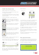
In filtration position
In cleaning position
1. The piston compresses the disc cartridge.
2. The conical flexible non-return membrane remains
open, allowing filtered water to go to the network.
1. The backwash valve inverts clean water flow into the
filter, closing the conical flexible non-return membra-
ne. This forces clean water through the three spine
manifolds that spray out tangentially the dirtiness from
the discs.
2. At the same time, the upper piston is compressed by
incoming pressure through the spine manifolds, relea-
sing the discs that spin in a centrifugal movement at
high speed.

