19
Setup
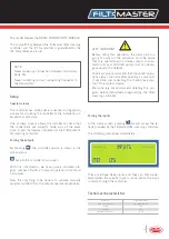
Special screens
The controller has some special advanced configuration
screens for adjusting the controller to the installation on
exceptional occasions.
One of these screens allows the installer to check that
the connections are correctly made and, at the same
time, to test the devices connected to the Filtmaster fil-
ter cleaning controller.
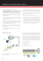
Testing the outputs
By pressing
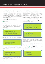
, the controller version is shown in the
screen status.
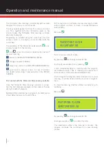
back to the controller main screen.
With this combination, we have quickly activated pro-
gram number 20 with a 5 second operation time for all
16 outputs.
Now, the only thing to be done is to activate manually
program number 20 so the outputs operate sequentially.
Technical characteristics
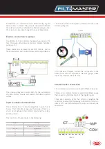
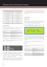
Testing the inputs
In the status screen, pressing
F
we will access the re-
ports provided by the Filtmaster filter cleaning controller.
The following will appear immediately:
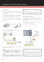
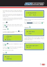
They are voltage-freee inputs and they can only be de-
tected when the specific input is connected to the input
common through the controller.
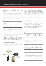
This model requires the RADIO CONNECTIVITY MODULE.
The compatibility between the Filtmaster filter cleaning
controller and the ICT transmitter is guaranteed by the
ICT Transmitter version 6.
NOTE
Never make any connection between controllers
while ON.
Never do testing without connecting the aerial to
the transmitter.
VERY IMPORTANT
Before doing this operation, the person who is
going to carry out the activation must be aware
that this operation will activate outputs connec-
ted to pumps or fertilizer pumps that can dama-
ge seriously the network.
That is why we recommend that these test opera-
tions always are done after opening a valve and,
if possible, disconnecting the three-phase star-
tup of the motors startup.
Precautionary, we recommend deleting this pro-
gram before definitively programming the filter
cleaning controller.
----
----
Dimensions
250 x 190 x 120 mm
Pin 6 conector modem
PIN 2 CONTROLLER
Weight
2 Kg
Material
ABS
Dust/water protection
IP-56
INPUTS


