User’s Manual
23
2.4.16 LED
There are 1*Power on LED, 1*HDD Run LED, 3*CPU temperature class LEDS on the front. CPU
temperature class LEDs(Green(≤85℃)/Yellow(≥86℃and≤95℃)/Red(≥96℃). Users can monitor the
working state of the CPU according to the display of the LED.
2.5 Installation
2.5.1 HDD/SSD Installation
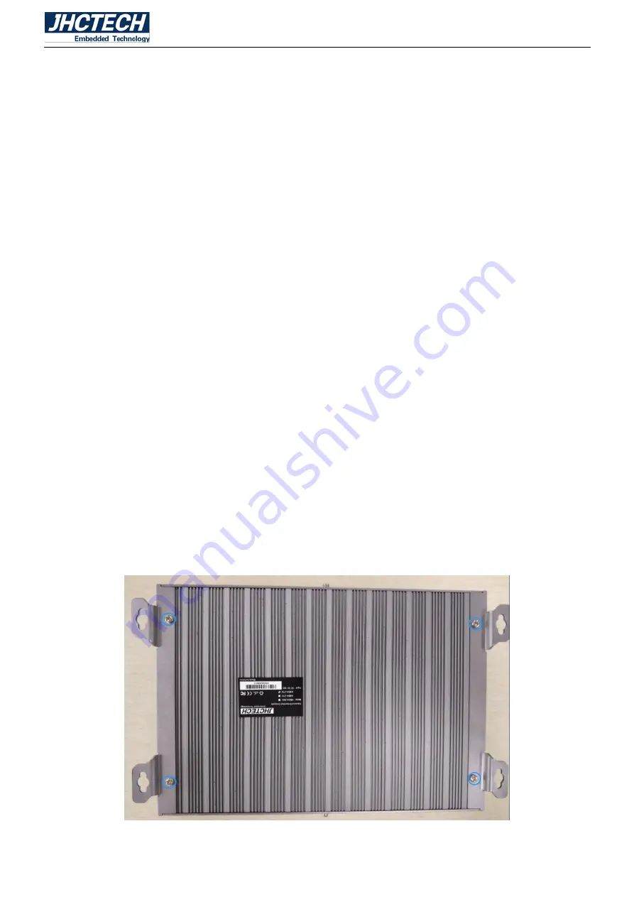
Step 1: Unscrew 4 screws on the underside, remove the bottom bracket.
Step 2: Unscrew 2 screws on the front/rear panel.
Step 3: Unscrew the spring pad and nut of the DC-IN on the front panel, Unscrew 6 serial copper columns
and 5 screws on the front panel.
Step 4: remove the front panel and the bottom cover.
Step 5: Put the HDD/SSD in the drive bay and screw 4 screws.
Step 6: Pull the drive bay onto the bottom cover and screw 4 screws.
Step 7: Using the SATA cable connect the HDD/SSD with the mother board.
Step 8: Close the bottom cover back to the chassis. install the front panel and screw 2 screws on the
front/rear panel.
Step 9: Screw 5 screws and 6 serial copper columns on the front panel. Lock the spring pad and nut of the
DC-IN on the front panel.
Step 10: Install the bottom bracket, screw 4 screws.
Figure 2.27
Summary of Contents for KMDA-2702
Page 1: ...User s Manual 1 User s Manual KMDA 2702 Ver A1 0 Date 15 October 2018 ...
Page 2: ...User s Manual 2 Version Note No Ver Note Date Writer 1 A1 0 first publish 20180815 Tracy Liu ...
Page 8: ...User s Manual 1 General Information CHAPTER 1 ...
Page 12: ...User s Manual 5 Main board rear Figure 1 1 Sub board ECB 153 Figure 1 2 ...
Page 13: ...User s Manual 6 Sub card ECD 7150 Figure 1 3 KMDA 2702 Dimensions Uint mm Figure 1 4 ...
Page 14: ...User s Manual 7 Hardware Installation CHAPTER 2 ...
Page 31: ...User s Manual 24 Figure 2 28 Figure 2 29 Figure 2 30 ...
Page 32: ...User s Manual 25 Figure 2 31 Figure 2 32 Figure 2 33 ...
Page 33: ...User s Manual 26 Figure 2 34 Figure 2 35 Figure 2 36 ...
Page 35: ...User s Manual 28 Figure 2 39 Figure 2 40 Figure 2 41 ...
Page 36: ...User s Manual 29 Figure 2 42 Figure 2 43 Figure 2 44 ...
Page 38: ...User s Manual 31 Figure 2 47 Figure 2 48 Figure 2 49 ...
Page 39: ...User s Manual 32 Figure 2 50 Figure 2 51 Figure 2 52 ...
Page 41: ...User s Manual 34 BIOS Setup CHAPTER 3 ...
Page 61: ...User s Manual 54 Driver Installation CHAPTER 4 ...


