


PDL5 User Manual
PDL5-UM-00001 Rev 001
37
7.
Using the dusting gas or compressed air, blow the areas cleaned.
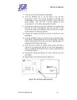
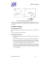
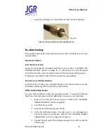
Figure 15: Connector (Connector Type May Vary)
Troubleshooting
If any problem described in this section persists, contact JGR Optics or your local
representative.
Connector Issues
Front Panel Connectors
Follow the maintenance procedure described in the section: “CLEANING THE
CONNECTOR ENDS” section on page 35, to ensure that the internal pigtail
connectors are clean and properly connected to the front panel mating sleeve.
If cleaning is not sufficient, the FC/APC connector can be polished.
Connector Loss and Backreflection
Ensure that the insertion loss and backreflection of all the connectors are low
and stable, complying with the connector specifications.
PDL5 Calibration Issues
To verify PDL5 calibration, follow the procedure below. If results are different
than those indicated, please contact JGR Optics to have your unit calibrated.
1.
Make sure to clean front panel connector. Refer to the “CLEANING
CONNECTOR ENDS” section on page 35.
2.
Turn PDL5 meter to ON
3.
Leave meter in BR measurement mode
4.
Verify the calibrated jumper to make sure it is not damaged and
that all connectors are cleaned. Refer to the “CLEANING JUMPER
CONNECTORS” section on page 36 if necessary.
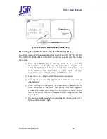
5.
Connect the APC end of the calibrated jumper to the APC connector
of the source
Ferrule