background image

 
Installation & Operation manual of Jetmaster Vent Free range 


Page 3 

Revision 01/09 


PLEASE READ ALL RELEVANT INSTRUCTIONS IN THIS MANUAL 
BEFORE STARTING ANY WORK ON THE UNIT 

 
INSTALLERS should read all sections of this manual 
 
END USERS: should read all 

operation

 and 

maintenance

 instructions. 

Summary of Contents for 700 Vent Free Built in

Page 1: ......

Page 2: ...IONS 4 WARNINGS 4 INSTALLATION INSTRUCTIONS 5 GENERAL 5 CLEARANCE DISTANCES AND MATERIALS 5 VENTILATION 5 OUTER BOX INSTALLATION 6 GAS BURNER INSTALLATION 7 GRANULAR VERMICULITE 8 CERAMIC PEBBLE LAYOUT 8 GLASS BEAD LAYOUT 8 COMMISSIONING 9 OPERATION INSTRUCTIONS 10 GENERAL 10 TURNING ON OFF 10 MAINTENANCE 11 SCHEDULED MAINTENANCE 11 FAULT FINDING 11 WARRANTEE 12 ...

Page 3: ... Vent Free range Page 3 Revision 01 09 PLEASE READ ALL RELEVANT INSTRUCTIONS IN THIS MANUAL BEFORE STARTING ANY WORK ON THE UNIT INSTALLERS should read all sections of this manual END USERS should read all operation and maintenance instructions ...

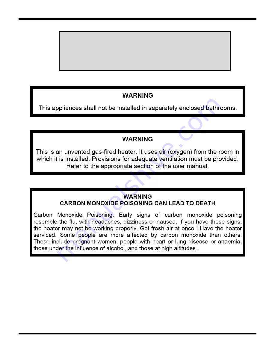
Page 4: ...iate regulator that can maintain the operating gas supply pressure during use and that complies with the requirements of SANS 1237 NOTE We suggest that you check the Data Plate on your Gas Burner and verify the Model on the above table for future reference WARNINGS Do not place articles on or against this appliance Do not use or store flammable materials near this appliance Do not spray aerosols i...

Page 5: ...ustible hearth is used NOTE Hot air rises from the front of the unit Any item like ornaments or televisions located directly above the fireplace will be heated by this hot air Care should be taken to diffuse this heat when locating placing sensitive items above the fireplace VENTILATION Fire uses oxygen to burn thus it s important to provide enough fresh air for the combustion process In addition ...

Page 6: ...on into a bricked wall is used to explain all installation requirements The same distances and guidelines apply to all other installation layouts STEP 1 Prepare the structure to allow for a cavity of at least the dimensions specified in the table below MODEL L D H 700 BI 770 305 535 The base on which the unit will rest must be constructed of non combustible materials and it is recommended that a n...

Page 7: ...from the front of the box GAS BURNER INSTALLATION It is recommended that the gas supply to the unit be routed through the right hand side panel so that a straight pipe run to the gas connection can be made The gas supply can also be routed through the back or bottom panels An adequate hole can be drilled in a position that would be hidden by the burner tray The gas burner is located into the box r...

Page 8: ... the full cross section of the vermiculite NOTE Pebbles must only be placed in 1 layer Do not place a second layer of pebbles Only use the pebbles supplied by the manufacturer never substitute for a different pebble This might cause unacceptable combustion levels GLASS BEAD LAYOUT Spread a single layer of glass beads over the vermiculite This layer should be no more than 5mm thick Some vermiculite...

Page 9: ...t periods only and repeat if necessary The gas pressure to the burner is as stated on the data label For LPG this is 2 8 kPa Verify that the gas pressure is in excess of this value NOTE The gas pressure measured when there is no gas flowing through the burner will always be higher than when the burner is functioning and gas is flowing through it With the pressure gauge still connected to the inlet...

Page 10: ...rm the turning action several times to create several sparks until the flame ignites When the flame is established in the pilot burner keep the knob depressed for at least another 10s This allows the safety valve to activate and to keep the gas supply to the pilot burner open Release the knob and verify that the pilot burner is burning stable IGNITING THE MAIN BURNER Depress the valve knob and tur...

Page 11: ...ell Immediately close the gas supply to the unit Contact a service technician Unit does not ignite after several spark attempts Check that gas supply is open Ensure that gas supply line has been purged from air in line If problem persist contact service technician No spark is generated when unit is switched ON Ensure that the igniter cable is connected tightly to the pilot burner Ensure that the i...

Page 12: ...ten years from the invoiced date of purchase This warranty is only effective if At the time of the claim the then owner of the Burner or firebox produces documentary evidence to prove the date of purchase e g The original or a true copy of the invoice The warranty card was fully completed and returned to Jetmaster by mail or by fax within 30 days of purchase A registered installer installed the Bu...

Reviews: