12
6.2
Tools required for assembly
Hex (Allen) wrenches: 4, 5, 6mm
Open end wrenches: 10, 13mm
Cross point (Phillips) screwdriver
Straight edge
Rubber mallet (or hammer with block of wood)
Level
Note: A ratchet wrench with sockets will speed
assembly time. Additional tools may be needed for
adjustments and/or assembly of fence and rails.
The main saw unit is heavy;
use an assistant or a hoist mechanism when
moving or turning it right side up.
6.3
Unpacking and cleanup
1. Remove all contents from shipping carton and
from inside of saw body. Do not discard carton
or packing material until saw is assembled and
running satisfactorily.
2. Inspect contents for shipping damage. Report
damage, if any, to your distributor.
3. Compare contents of shipping carton with the
contents list in this manual. Report shortages,
if any, to your distributor. Check machine first
to see if parts have been pre-installed.
4. Slide table saw off pallet onto cardboard or
pad to prevent scratching table surface. Keep
saw upside down.
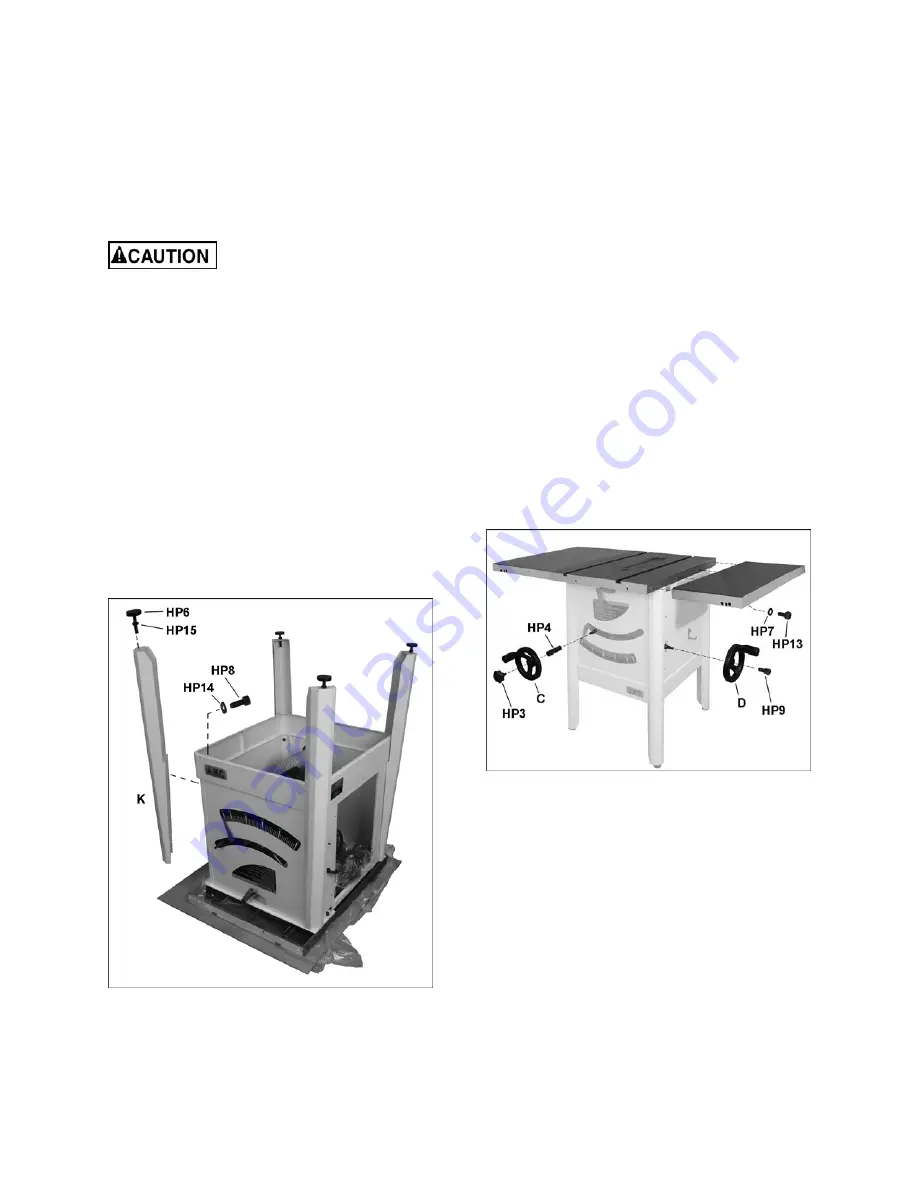
Figure 6-3
6.4
Installing legs and levelers
See Figure 6-3.
1. Mount legs (K) to cabinet using two M8 screws
with washers (HP8/13) into each leg as shown.
Install both screws first, then tighten with 5mm
hex wrench. (Note: If more clearance is
needed to insert a screw, see
sect. 6.6
to
temporarily mount a handwheel and tilt the
trunnion out of the way.)
2. Install four levelers with hex nuts (HP6/14).
3. Turn saw right-side up and allow the feet to
adjust to floor surface. Place a level on table,
and adjust the levelers as needed. Tighten hex
nuts up against leg with 10mm wrench to
secure setting.
6.5
Extension wings
See Figure 6-4.
Wings are available in cast iron or stamped steel.
Make sure mating surfaces are clean and free of
burrs.
Attach each extension wing to saw table using four
screws and washers (HP7/13). Do not fully tighten
yet.
Assembly Tip:
If you are doing this without an
assistant, lift extension wing perpendicular to table
edge. Install a center screw and washer, and make
snug. Then pivot wing parallel to saw table to insert
remaining three screws.
Figure 6-4
6.5.1
Leveling extension wings
Note: The following instructions show assembly of
the
cast
wings. The
stamped steel
wings may have
a tendency to sag until rails are installed, and may
need further leveling adjustments during rail
installation.
Level extension wings to saw table using a straight
edge. A metal straight edge is ideal, though a
carefully jointed board may also be used.
Two methods are described below: one using a
rubber mallet, the other using clamps on the table
edges.
Summary of Contents for ProShop II JPS2-115
Page 28: ...28 14 1 1 Motor and Trunnion Exploded View...
Page 32: ...32 14 2 1 Table and Cabinet Exploded View...
Page 36: ...36 14 5 1 Blade Guard Assembly Exploded View...
Page 41: ...41 This page intentionally left blank...
Page 42: ...42 This page intentionally left blank...
Page 43: ...43 This page intentionally left blank...
Page 44: ...44 427 New Sanford Road LaVergne Tennessee 37086 Phone 800 274 6848 www jettools com...


