9
If hardwired:
Permanently connected tools: This tool should be
connected to a grounded metal permanent wiring
system; or to a system having an equipment-
grounding conductor. Make sure a disconnect is
available for the operator. During hard-wiring of the
machine, make sure the fuses have been removed
or the breakers have been tripped in the circuit to
which the drill press will be connected. ALWAYS
FOLLOW PROPER LOCK-OUT/TAG-OUT PRO-
CEDURES.
6.2
Extension cords
The use of extension cords is discouraged; try to
position equipment within reach of the power
source. If an extension cord becomes necessary, be
sure it is heavy enough to carry the current your
product will draw. An undersized cord will cause a
drop in line voltage resulting in loss of power and
overheating.
Table 2 shows recommended size to use depending
on cord length and nameplate ampere rating. If in
doubt, use the next heavier gauge. The smaller the
gauge number, the heavier the cord.
Ampere
Rating
Volts
Total length of
cord in feet
More
Than
Not
More
Than
240 50 100
200 300
AWG
0 6
18
16
16 14
6 10
18
16
14 12
10 12
16
16
14 12
12 16
14
12
Not
Recommended
Extension Cord Recommendations
Table 2
7.0
Adjustments
Disconnect machine from
power source before making adjustments,
unless indicated otherwise.
7.1
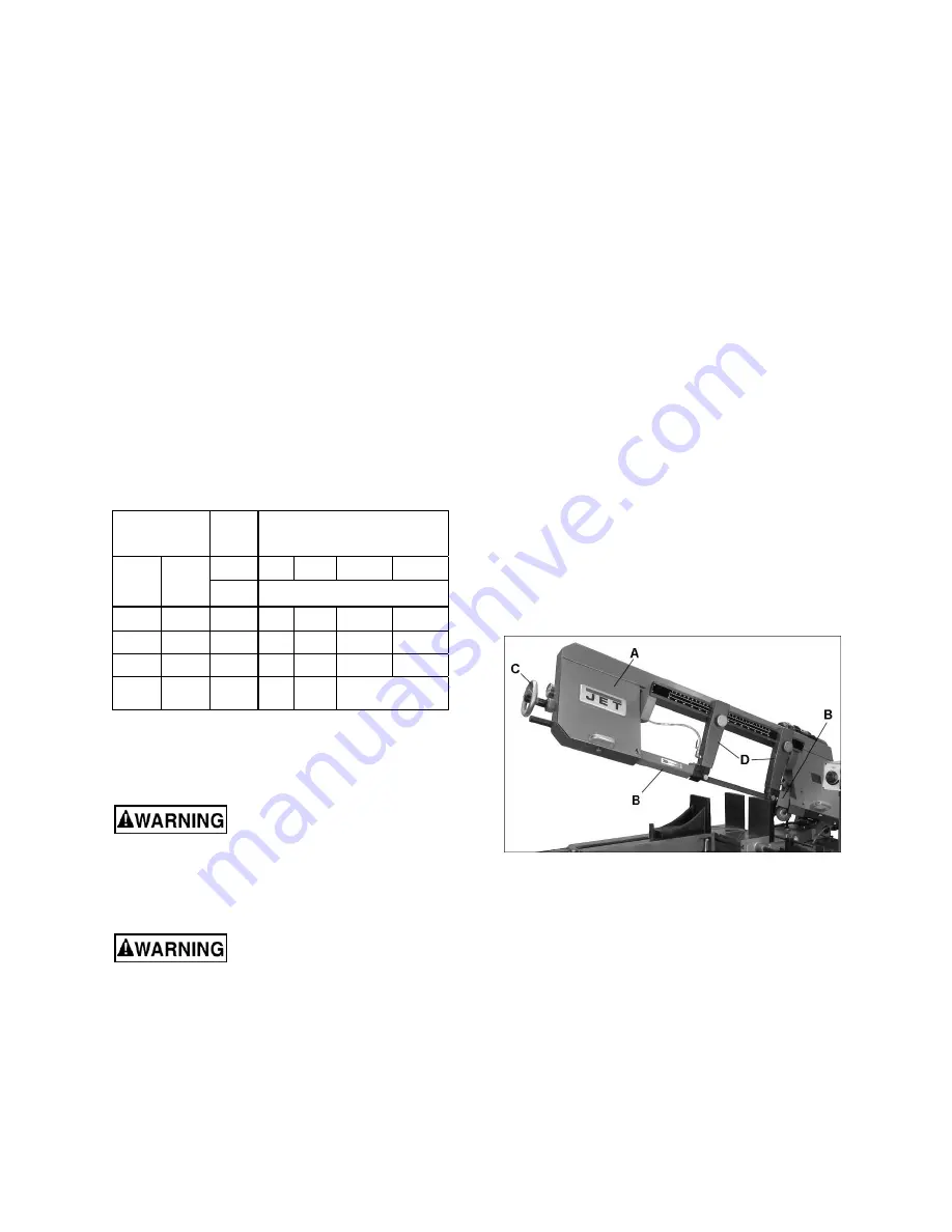
Blade installation and removal
Refer to Figure 7-1.
Always wear leather gloves
when handling blades to avoid injury.
A blade (1-1/4 in. W x 172 in. L) is pre-installed and
tensioned on saw. To replace blade:
1. Raise bow about 15-degrees and keep it in
raised position by turning feed rate control knob
clockwise all the way (see
sect. 8.0
).
2. Disconnect machine from power source.
3. Open both wheel covers (A, Figure 7-1) and
clean out any swarf from wheel areas.
4. Remove red blade guards (B).
5. Back off the blade guides by loosening knob (H,
Figure 7-2). Back off the wire chip brush.
6. Release blade tension by turning blade tension
handwheel (C) counter-clockwise.
7. Remove blade from both wheels and out of
each blade guide.
8. Make sure teeth of new blade are pointing in
direction of travel. If necessary, turn blade
inside out.
9. Position new blade around wheels and through
upper slot. Slide it into blade guide bearings
with back edge of blade contacting backup
bearing. (see Figure 7-2). For further guide
bearing adjustment, see
sect. 7.3
10. Lightly increase tension (C) and position blade
so it rests against shoulder of both wheels.
11. When blade is properly positioned, place full
tension upon it (see
sect. 7.4.1
).
12. Reinstall blade guards (B).
13. Adjust chip brush up against blade teeth.
14. Jog the start/stop buttons to ensure blade is
tracking properly. If tracking adjustment is
needed, see
sect. 7.4.2
.
15. Close wheel covers.
Figure 7-1: blade changing
7.2
Guide post adjustment
The blade guide posts (D, Figure 7-1) must be set
to just clear the workpiece, but should not interfere
with workpiece or other saw components during
bow’s descent.
Loosen knobs and slide posts into position. Always
tighten knobs before operating machine.
7.3
Blade guide adjustment
The bearing and carbide guides come pre-adjusted
from the factory for the installed blade. If adjustment
is needed, or if a blade is replaced, follow the below
steps for left and right guides.


