22
Adjustments
Blade Raising and Tilt Mechanism
Never try to force the tilting
mechanism past the 45º or 90º stops! This may
cause the blade to go out of alignment!
To
raise or lower
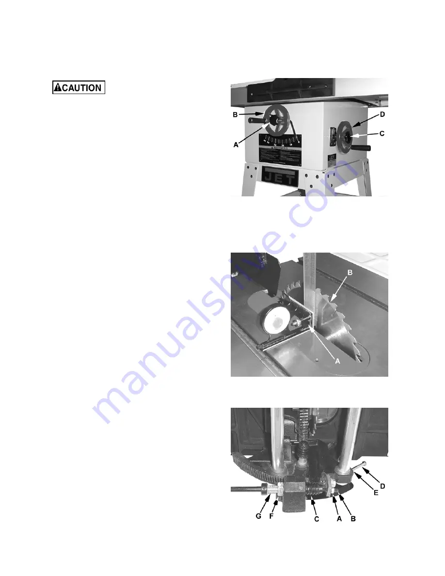
the saw blade, loosen the lock
knob (A, Fig. 29) and turn the handwheel (B, Fig.
29) until the desired height is reached. Tighten the
lock knob. The blade should be adjusted between
1/8" to 1/4" above the top surface of the material
being cut.
To
tilt
the saw blade, loosen the lock knob
(C, Fig. 29), turn the handwheel (D, Fig. 29) until
the desired angle is obtained, then tighten the lock
knob.
Adjusting 45º and 90º Positive Stops
1. Disconnect the saw from the power source.
2. Raise the table saw blade to its maximum
height using the handwheel.
3. Set the blade at 90º to the table by turning the
blade tilting handwheel counterclockwise
(D, Fig. 29) as far as it will go. Do not force
beyond stop.
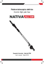
4. Place a square (A, Fig. 30) on the table and
check to see that the blade (B, Fig. 30) is at a
90º angle to the table. Make sure that the
square is not touching a blade tooth.
Adjustment, if required, is performed on the gear
mechanism located underneath the table as shown
in Figure 31 and described in the following steps.
Referring to Figure 31:
5. If the blade is not at 90º, loosen the lock nut (A)
and turn the adjusting stop screw (B) in or out.
The adjusting stop screw (B) should stop
against the end of the tilting screw (C) when
the blade is 90º to the table.
6. Place a square on the table after turning the
blade to the 45º stop (Figure 32). If the 45º
positive stop is not set properly, follow the
same procedure using the
screw
(D) and l
ock
nut
(E) (not visible in photo).
7. Check the cursor accuracy and adjust, if
necessary.
Figure 29
Figure 30
Figure 31
Summary of Contents for JWTS-10JF
Page 34: ...34 JWTS 10JF Exploded View...
Page 35: ...35...
Page 37: ...37 JETFENCE Exploded View...
Page 39: ...39 Wiring Diagram...


