Jet JSG-6DC Operating Instructions And Parts Manual Download Page 16


16

Adjust 90° Stop 

6.  With the table locked at 90°, loosen the hex 

nut on the 90° stop, and adjust the set 
screw to seat against the stop block. See 
Figure 19. Re-tighten hex nut to secure the 
setting. 

7.  If angle indicator adjustment is necessary, 

loosen the screw and shift the pointer to 
zero, and re-tighten the screw. 

Adjust 45° Stop 

8.  Flip the stop block out of the way, and tilt 

the table down to 45°. Verify the setting of 
the 45° angle stop (Figure 19). Use the 
same procedure as above but with a 45° 
measuring device on the table. Correct the 
stop as needed. 

Belt Arm Orientation 

Loosen the belt arm lock screw (see Figure 13) 
to tilt the belt arm to vertical or horizontal 
position. The belt arm can also be secured at 
any angle between. Always tighten the screw 
before operating. 

Note:

 Belt tracking may require re-adjustment if 

the belt assembly is moved from vertical to 
horizontal or back again. 

Limit Screw Adjustment 

This set screw (Figure 22) limits the rotation of 
the belt arm to vertical and horizontal positions, 
and has been pre-set. If it should ever need re-
adjustment: 

1.  Loosen lock nut on the set screw with a 

10mm wrench. 

2.  With a 3mm hex key, turn set screw all the 

way in until it bottoms out. Back screw out 
three turns and re-tighten lock nut, while 
holding screw in place. 

Disc Table Adjustment 

1.  Disconnect machine from power source. 

2.  Place a square on the table and against the 

disc. See Figure 23. Loosen both lock 
knobs, move the table until the square sits 
flush to both surfaces at 90°, and re-tighten 
both knobs. Note: You may need to pivot 
the stop block out of the way. 

3.  Place a combination square in the miter 

gauge slot and check the distance from the 
slot to face of the disc. See Figure 24. Slide 
the square along the slot to the other side of 
the disc and check the distance. The 
distances should be equal to ensure that the 
miter gauge travels parallel to the disc.  


Figure 22 


Figure 23 


Figure 24 

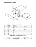
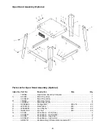
Summary of Contents for JSG-6DC

Page 1: ...der Model JSG 6DC with optional open stand with optional closed stand WALTER MEIER Manufacturing Inc 427 New Sanford Road LaVergne Tennessee 37086 Part No M 708598 Ph 800 274 6848 Revision G 03 2010 w...

Page 2: ...ge prepaid to a location designated by us For the name of the location nearest you please call 1 800 274 6848 You must provide proof of initial purchase date and an explanation of the complaint must a...

Page 3: ...ction 15 Adjustments 15 Belt Table Adjustment 15 Belt Arm Orientation 16 Limit Screw Adjustment 16 Disc Table Adjustment 16 Miter Gauge 17 Belt Tracking Adjustment 18 Belt Replacement 18 Abrasive Disc...

Page 4: ...activities contains chemicals known to cause cancer birth defects or other reproductive harm Some examples of these chemicals are Lead from lead based paint Crystalline silica from bricks cement and o...

Page 5: ...ool and changing accessories 28 Support the workpiece adequately maintain control of the work at all times 29 Avoid kickback by sanding in accordance with directional arrows When disc sanding sand on...

Page 6: ...lt Table L x W in 14 3 4 x 7 1 2 Miter Groove in 3 4 x 3 8 Belt Speed SFPM 2500 Belt Table Positive Stops deg 45 and 90 Disc Section Disc Diameter in 12 Arbor Size in 3 4 Disc Table Tilt deg 25 to 45...

Page 7: ...by young children the use of a padlock is highly recommended A padlock stock no 709012 A is available from your local authorized JET distributor or by calling Walter Meier Manufacturing Inc at the pho...

Page 8: ...g grounding plugs and three pole receptacles that accept the tool s plug Repair or replace a damaged or worn cord immediately 115 Volt Operation As received from the factory your sander is wired to ru...

Page 9: ...mended that the JSG 6DC Belt Disc Sander when operated at 230 volt be connected to a grounded and dedicated minimum 15 amp circuit with a 15 amp circuit breaker or time delay fuse Local codes take pre...

Page 10: ...your distributor Read the instruction manual thoroughly for assembly maintenance and safety instructions Contents of Main Carton See Figure 8 1 Belt Disc Sander A 1 Belt Sanding Table B 1 Disc Sanding...

Page 11: ...ware bag contains the same fasteners as the sander hardware bag and will not be needed if you purchased sander and stand together Contents of Open Stand Carton Optional Accessory p n 708566 See Figure...

Page 12: ...ers flat washers and hex nuts Tighten hex nut while holding the screw head stationary using two 11 16 wrenches Remove lifting straps 4 Exposed metal surfaces have been factory coated with a protectant...

Page 13: ...htening the nut with a 4mm hex wrench When the nut is fully tightened onto the stud release the handle making sure it seats itself back onto the nut Note The table lock handle can be repositioned at a...

Page 14: ...ructions may result in premature belt breakage 5 Once the belt direction has been determined pull the belt tensioning handle toward you with one hand while using the other hand to slide the belt onto...

Page 15: ...source 2 Place a square on the table and up against the platen or abrasive belt as shown in Figure 19 3 Loosen the table lock handle and move the table until the square sits flush to both surfaces at...

Page 16: ...tical to horizontal or back again Limit Screw Adjustment This set screw Figure 22 limits the rotation of the belt arm to vertical and horizontal positions and has been pre set If it should ever need r...

Page 17: ...the angle with a 45 measuring device on the table and against the disc 7 If adjustment is necessary loosen the hex nut turn the stop screw as needed and re tighten the hex nut to secure the setting Ad...

Page 18: ...D Figure 28 and slide belt off the wheels 4 Refer to Installing Abrasives section for instructions on installing the new belt Abrasive Disc Replacement 1 Disconnect machine from the power source 2 Slo...

Page 19: ...Arrows on abrasive belt and machine should be pointing same direction Sanded edge not square Table not square to abrasive belt Use a square to adjust table to abrasive belt Miter slot not parallel to...

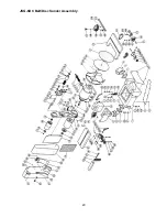
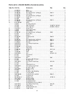
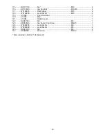
Page 20: ...20 JSG 6DC Belt Disc Sander Assembly...

Page 21: ...W Bracket 1 22 SR080700 Hex Socket Cap Screw M8x35 1 23 NH061000 Nut M6 1 24 SS060600 Set Screw M6x30 1 25 610010 Stop Block 1 26 PS054500 Spring Pin 5x45 mm 1 27 612011 Scale 1 28 VS020500 Rivet M2x5...

Page 22: ...Cap Bolt M8x16 4 83 WF081818 Flat Washer M8 4 84 WS080000 Lock Washer M8x 4 85 612038 Trunnion Bracket 1 86 990551 Knob 2 87 612039W Sanding Table 1 88 612040W Trunnion 1 89 612041 Sliding Plate 1 90...

Page 23: ...ock Washer M10 4 119 612052 Trunnion Holder 1 120 612053 Stud 1 121 612054 Table Bracket 1 122 NH081300 Nut M8 1 123 SR080500 Hex Socket Cap Screw M8x25 1 124 WS060000 Lock Washer M6 1 125 WS080000 Lo...

Page 24: ...150103 Stop 2 7 TS 1523031 Set Screw M6 x 10 2 8 612063 Stop Shaft 1 9 PS042400 Spring Pin 4 x 24 mm 1 10 150106 Spring 1 11 150104 Step Plate 1 12 145002 Door 1 13 150503 Lock 1 14 150527 Pad 2 Hardw...

Page 25: ...2049W Stand Top white 1 B 150603 Stand Leg blue 4 150603W Stand Leg white 4 C SC089400 Carriage Bolt M8 x 16 40 D WF081818 Flat Washer M8 40 E WS080000 Lock Washer M8 40 F NH081300 Hex Nut M8 40 G 612...

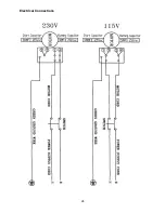
Page 26: ...26 Electrical Connections...

Page 27: ...27...

Page 28: ...28 WALTER MEIER Manufacturing Inc 427 New Sanford Road LaVergne Tennessee 37086 Phone 800 274 6848 www waltermeier com...

Reviews: