8
Raising the Head
The drill press head is lowered on the column for
crating and transportation. Before operating the
drill press, the head will need to be raised to the
operational level.
To raise the head:
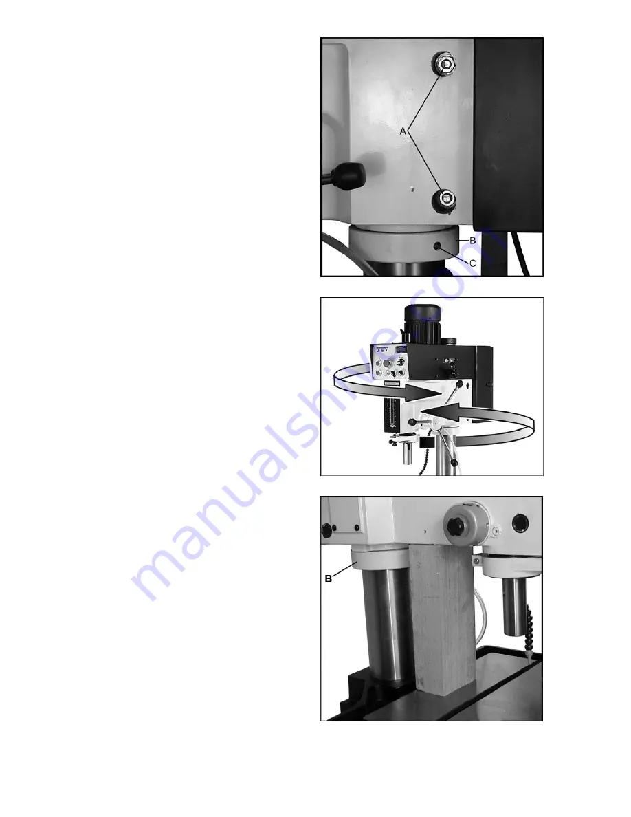
1. Loosen the two head locking bolts (A, Figure
4) by turning counterclockwise.
Make sure the
two screws (C, Figure 4) in the lock collar (B)
are tight.
2. Take the head and turn it slightly from side to
side (Figure 5) to loosen the rust prevention
solution on the column
3. Loosen the table lock by placing the handle on
the crankshaft (A, Fig. 7) and rotating the
handle counter-clockwise
4. Cut a 2x4 approximately 16” in length.
5. Raise the table by placing handle on
crankshaft (B or C, Figure 7) and rotating
clockwise. Snug the 2x4 between the table
and the head as close to the column as
possible.
Caution:
Do not place the 2x4 under
the lock collar (B, Fig. 6).
6. Use the table lift crank on a shaft (B or C, Fig.
7) to raise the head and 2x4 until the head
bore and the column are flush.
CAUTION:
When the head bore and the column cap are
flush, the head cannot be raised anymore. Use
a ladder to observe the column through the top
of the belt cover.
7. Tighten the two head locking bolts (A, Fig. 4).
This will hold the head in place until the lock
collar can be moved into position. The 2x4 can
now be safely removed.
8. After the head is set at the desired height,
loosen two set screws (C, Fig. 4) on the lock
collar.
9. Slide the lock collar up the column until it is
flush with the head.
10. Firmly tighten the two setscrews on the lock
collar (C, Fig. 4).
To lower the head, reverse the steps above.
Do
not
loosen the head locking bolts without
supporting the head.
Figure 4
Figure 5
Figure 6
Summary of Contents for JDP-20EVS
Page 13: ...13 Top Head Assembly...
Page 16: ...16 Head Assembly...
Page 19: ...19 Control Panel Assembly...
Page 21: ...21 Electrical Cabinet Assembly...
Page 23: ...23 Column Table Base Assembly...
Page 28: ...28 Wiring Diagram 460 Volt 3 Phase...
Page 29: ...29 Wiring Diagram 230 Volt 1 3 Phase...
Page 30: ...30 This page intentionally left blank...
Page 31: ...31 This page intentionally left blank...
Page 32: ...32 427 New Sanford Road LaVergne Tennessee 37086 Phone 800 274 6848 www jettools com...


