background image

18

Adjusting guide bearings

There are eight side blade guide/support bearings.

These bearings are installed in the bearing seat, and the
seat is attached to the sliding adjustment bracket.

 These bearings are stacked, with 

two

 bearings on

each adjustment eccentric.  The width of each pair of
stacked bearings is slightly less than the width of a blade.

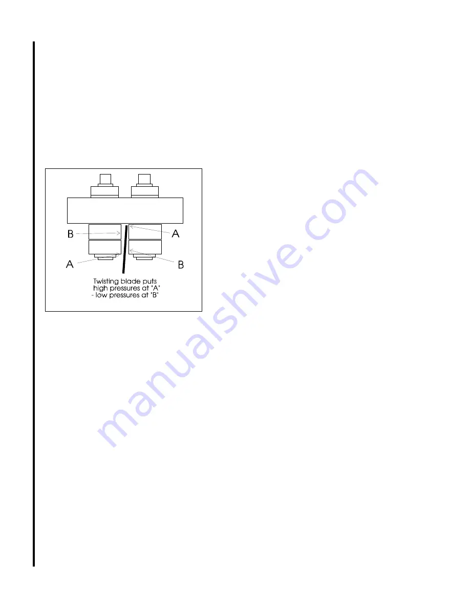
The force against each of the bearings in each

stack is not equal.  This is because the bearings are
twisting the blade.  This puts a much higher force against
the two bearings which are doing most of the twisting.
Look at 

Figure 15

 for a diagram which shows this effect.

Figure 15: Guide bearing forces.  Blade twist and clear-
ance is exaggerated for demonstration.  In practice, the
blade will be standing vertical between the bearings when
they are adjusted correctly.

The bearings are adjusted by moving the eccentrics

as required, and by using your fingers to twist the bear-
ings to see if they can rotate, and how difficult it is to
rotate them.

The bearing clearance is correctly adjusted when

the bearings labeled with an "A" in 

Figure 15

 cannot be

turned at all, and when bearings labeled with a "B" in

Figure 15

 can 

barely

 be turned with your fingers.

If the supporting bearings don't turn at all -- the set-

up is too tight.  If they can be turned easily using your
thumb and forefinger -- the set-up is too loose.
To adjust:
1.  Put a wrench on the adjustment tang of the bearing set
you want to adjust.  This prevents the eccentric from
turning.
2.  Use another wrench to loosen the lock nut for the
eccentric bolt.
3.  Turn the eccentric using the adjustment tang to loosen
or tighten the bearing set, as needed.
4.  Tighten the jam nut.
5.  Check bearing tightness on both sides of the blade.
Re-adjust as required until the conditions described in the
above paragraphs is obtained.

Replacing guide bearings

1.  Remove the blade as outlined in steps 1


through 6 of

Replacing blades

.

2.  Remove the jam nut on the eccentric upon which you
are going to replace bearings.
3.  Remove the clip which secures the bearings on the
eccentric shaft.
4.  Tap the old bearings off and press the new bearings
on.
5.  Replace the snap ring which secures the bearings on
the eccentric.
6.  Reinstall the eccentric in its position and tighten the
jam nut loosely on the eccentric.
7.  Install the blade according to instructions 7


through 14

in 

Replacing blades

.

8. Adjust bearing clearance according to instructions in
the previous section: 

Adjusting guide bearings

.

Adjusting blade
back-up bearings

The back-up bearings support the rear of the saw

blade as it takes the pressure of cutting.  (Refer to

Figure 11

.)

1.  Being careful not to disturb the vertical angle of the
guide bearing seat, loosen the socket head cap screw
which secures the seat.
2.  Move the seat downward until the back-up bearing just
barely touches the back of the blade.
3.  Tighten the socket head cap screw securely.
4.  Perform this same operation on the other back-up
bearing, if required.

After adjusting the back-up bearings, CHECK FOR

BLADE VERTICAL according instructions in 

Adjusting

blade vertical

.  It is very easy to disturb the vertical plane

of the blade while performing this adjustment, and a blade
which is not vertical will NOT cut straight.

Summary of Contents for J-3410

Page 1: ...tructions and Parts Manual 7x12 Horizontal Band Saw Models J 3410 J 3410 2 JET 427 New Sanford Road LaVergne Tennessee 37086 Part No M 414454 Ph 800 274 6848 Revision B3 01 2014 www jettools com Copyr...

Page 2: ...More Information JET Wilton and Powermatic are consistently adding new products For complete up to date product information check with your local distributor or visit the JET Wilton or Powermatic webs...

Page 3: ...Adjust Blade for Parallelism 16 Adjusting Blade Vertical 17 Test Cutting to VerifyAdjustmentAccuracy 17 Adjusting Guide Bearings 18 Replacing Guide Bearings 18 Adjusting Blade Back Up Bearing 18 Repl...

Page 4: ...ystem which can greatly extend blade life and speed the cutting of a variety of materials which are best cut with cutting fluids and coolants 1 gallon 4 4L capacity tank with 3GPM 13L M pump Optional...

Page 5: ...se the right tool Don t force a tool or attach ment to do a job it was not designed for 16 Use only recommended accessories and follow manufacturers instructions pertaining to them 17 Keep hands in si...

Page 6: ...ustment of blade support mechanism is done or before any attempt is made to change the drive belts or before any periodic service or maintenance is per formed on the saw 7 Remove all loose items and a...

Page 7: ...can pivot and also tilt upward Therefore this nut should be slightly loose This will allow the jaw to pivot an conform to any angle at which the stationary jaw is set However you should guard against...

Page 8: ...or all angle cutting Changing the stationary vise jaw position 1 Remove the pivot and lock bolts 2 Slide the stationary jaw to the required position on the table 3 Re insert the pivot and lock bolts 4...

Page 9: ...Figure 1 4 Lay a straight edge on the saw frame so it contacts the stationary vise jaw See Figure 3 5 Turn the vise jaw until the straight edge is above the angle of cut you require as shown on the a...

Page 10: ...valve turn the quick shut off handle so it is parallel with the hydraulic line or hydraulic cylinder Using the stock stop for repeated cuts If you are cutting multiple pieces of stock all to the same...

Page 11: ...shape supplied Blade break in procedures New blades are very sharp and therefore have a tooth geometry which is easily damaged if a careful break in procedure is not followed You may want to consult m...

Page 12: ...Material Speed Angle cutting 1 Raise the saw arm to full height and lock it in position with the quick shut off valve 2 Slide the vise open 3 Set the stationary vise jaw to the angle required accordin...

Page 13: ...13 Figure 8 Placing workpieces in the vise...

Page 14: ...blade is fully tensioned release tension slightly before attempting to adjust the saw blade tracking A badly worn or bent blade will be extremely difficult to track properly if it can be tracked succe...

Page 15: ...sing the stationary vise face or the saw table When to adjust the blade guides The blade guides when installed at the factory have been adjusted for maximum sawing effectiveness and if not disturbed d...

Page 16: ...lishing a reference angle to be sure the jaw is correctly set 3 Lower the saw arm to full horizontal position 4 Use a machinist s protractor against the stationary vise jaw and check the blade for par...

Page 17: ...to perform these test cuts as follows 1 With the bar stock securely clamped in the vise make a cut through the bar stock See Figure 14 2 Mark the top of the bar stock 3 Move the bar stock about 1 4 in...

Page 18: ...loosen the lock nut for the eccentric bolt 3 Turn the eccentric using the adjustment tang to loosen or tighten the bearing set as needed 4 Tighten the jam nut 5 Check bearing tightness on both sides o...

Page 19: ...nce of leakage and turn them to feel for roughness or other internal flaws Replace if leaking or roughness is felt Examine the wheel for damage on its drive edge shoul der or the bearing mounting boss...

Page 20: ...emove piston from the rod 16 Remove the U ring from the piston 17 Remove the one external and the two internal O rings from the top cap Discard all soft parts 18 Clean all metal parts with a suitable...

Page 21: ...cal The saw is delivered as either a 115 volt or 230 volt saw depending upon your order Wiring diagrams for either type of circuit are shown here The motor is connected internally to achieve the volta...

Page 22: ...ubber disc mounted on a flat headed screw The screw height and therefore the horizontal position of the saw arm is adjusted using two nuts on the screw The motor switch is supposed to turn the motor o...

Page 23: ...e while observing chip formation to be sure you are cutting efficiently 1 Reduce speed of blade 2 Increase feed pressure in scale or hard spots 1 Work hardening materials such as stainless require a h...

Page 24: ...chip formation to verify efficient cutting 1 Increase blade speed Check technical literature or blade or workpiece supplier for blade speed recommenda tions 1 Be sure vise is tight 2 Support slender c...

Page 25: ...tion The item numbers shown on the illustration relate to the item number in the facing parts listing Order replacement parts from JET 427 New Sanford Road LaVergne Tennessee 37086 Ph 800 274 6848 www...

Page 26: ...26 Exploded View Saw Head...

Page 27: ...ot shown 1 1 J 5710011 Pulley cover 1 2 5710021 Motor pulley 1 4 1 5710041 HH screw 5 16X1 8 5 J 5710051Motor 3 4 HP 115V 1PH 1 6 J 5710061Motor mount plate assy 1 7 5710071 HH screw 5 16x5 8 3 8 5710...

Page 28: ...28 Exploded View Saw Base...

Page 29: ...ee support 1 111 5517529 HH screw 3 8x1 3 4 2 115 5711271 Support shaft 5 8 1 5711771 Support shaft 7 8 119 5711321 Stock stop 1 120 5711331 Thumb screw 1 121 5711341 Stock stop rod 1 123 5517530 HH s...

Page 30: ...der Ref no Part no Description Qty 1 5517547 Dust cover 1 2 5517548 Retaining ring 2 3 5517549 Oil seal 1 4 5517550 Oil piston 1 5 5517551 O ring 1 6 5517552 Cylinder body 1 7 5517553 Oil pressure reg...

Page 31: ...31...

Page 32: ...32 427 New Sanford Road LaVergne Tennessee 37086 Ph 800 274 6848 www jetttools com...

Reviews: