background image

32 


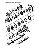
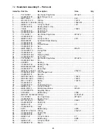
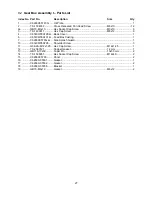
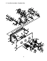
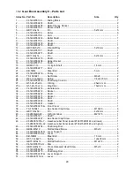
11.2

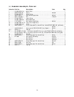
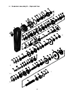
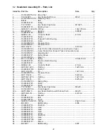
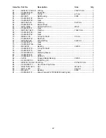
  Gear Box Assembly III – Parts List 

Index No.  Part No. 

Description 

Size 

Qty 

3 ............... C6140W05A730 ....... Shaft  (

I

) ................................................................  .................................... 1 

4  ............... C6266C05772J ........ Bearing  Cover ......................................................  .................................... 1 
5 ............... G51-1-.B-35x50x8 .... Oil  Seal ................................................................. B-35x50x8 ................... 2 
6 ............... BB-6305 ................... Ball Bearing .......................................................... 25x62x17 mm ............. 1 
7 ............... GB894.1-25 .............. C-Clip for Shaft .................................................... 25 mm ......................... 3 
8  ............... C6140W05731 ......... Double  Gear .........................................................  .................................... 1 
9 ............... BB-6203 ................... Ball Bearing .......................................................... 17x40x12 mm ............. 9 
10  ............. C6140W05732 ......... Gear .....................................................................  .................................... 1 
11 ............. BB-6205 ................... Ball Bearing .......................................................... 25x52x15 mm ............. 1 
12 ............. C6140W05A769 ....... Spacer ..................................................................  ....................................  5 
13  ............. C6140W05733 ......... Double  Gear .........................................................  .................................... 2 
14 ............. BB-6005 ................... Ball Bearing .......................................................... 25x47x12 mm ............. 5 
15  ............. C6140W05736 ......... Spacer ..................................................................  .................................... 1 
16 ............. GB1099-4x19 ........... Woodruff Key ....................................................... 4x19 mm ..................... 1 
17 ............. C6140W05A735 ....... Shaft  (

V

) ...............................................................  .................................... 1 

18 ............. C6140W05A738 ....... Shaft  (

VII

).............................................................  .................................... 1 

19  ............. C6140W05737 ......... Triple  Gear ...........................................................  .................................... 1 
20  ............. C6140W05739 ......... Gear .....................................................................  .................................... 1 
21 ............. C6140W05743 ......... Shaft (

VIII

) ...........................................................  .................................... 1 

22  ............. 16006 ....................... Bearing ................................................................. 30x55x9 mm ............... 2 
23  ............. C6140W05740 ......... Spacer ..................................................................  .................................... 2 
24  ............. BB-51106 ................. Thrust  Bearing  ..................................................... 30x47x11  mm ............. 2 
25 ............. C6140W05117-G ..... Flange Sleeve ......................................................  .................................... 1 
26 ............. GB70- M10x25 ......... Hex Socket Cap Screw ........................................ M10x25 ....................... 8 
28  ............. C6266C05773J ........ Sleeve ..................................................................  .................................... 1 
29  ............. C6266C05741J ........ Bearing  Cover ......................................................  .................................... 1 
30  ............. C6140W05742 ......... Round  Nut ............................................................  .................................... 2 
31  ............. C6140W05767 ......... Shaft .....................................................................  .................................... 1 
32 ............. GB117-6x40 ............. Taper Pin .............................................................. 6x40  mm ..................... 4 
33 ............. G38-4A-M16x1.5 ...... Plug ...................................................................... M16x1.5 ......................  2 
34 ............. C6140W05A771 ....... Bearing  Cover ......................................................  ....................................  1 
35 ............. BB-6303 ................... Ball Bearing .......................................................... 17x47x14 mm ............. 1 
36 ............. C6140W05A762 ....... Shaft  (

II

) ...............................................................   ....................................  1 

37  ............. C6140W05763 ......... Gear .....................................................................  .................................... 1 
38  ............. C6140W05764 ......... Gear .....................................................................  .................................... 1 
39  ............. C6140W05125 ......... Sleeve ..................................................................  .................................... 1 
40  ............. C6140W05751 ......... Sleeve ..................................................................  .................................... 2 
41 ............. C6140W05A752 ....... Adjust  Washer ......................................................  ....................................  2 
42 ............. C6140W05A754 ....... Shaft  (

IV

) ..............................................................  .................................... 1 

43 ............. C6140W05A759 ....... Gear  .....................................................................  ....................................  1 
44  ............. C6140W05758 ......... Gear .....................................................................  .................................... 1 
45  ............. C6140W05757 ......... Gear .....................................................................  .................................... 1 
46 ............. C6140W05A734 ....... Positioning  Sleeve  ...............................................  ....................................  2 
47 ............. GB75-M8x10 ............ Slotted Set Screw ................................................ M8x10 ......................... 2 
48  ............. C6140W05756 ......... Gear .....................................................................  .................................... 1 
49  ............. C6140W05755 ......... Gear .....................................................................  .................................... 1 
50  ............. C6140W05753 ......... Gear .....................................................................  .................................... 1 
51 ............. C6140W05A749 ....... Shaft  (

) ..............................................................  ....................................  1 

52  ............. C6140W05750 ......... Gear .....................................................................  .................................... 1 
53 ............. C6140W05A748 ....... Gear  .....................................................................  ....................................  1 
54 ............. C6140W05A124 ....... Sleeve ..................................................................  .................................... 1 
55  ............. C6140W05747 ......... Gear .....................................................................  .................................... 1 
56  ............. C6140W05746 ......... Gear .....................................................................  .................................... 1 
57 ............. C6140W05745 ......... Shaft (

IX

) ..............................................................  .................................... 1 


Summary of Contents for GH-26120ZH

Page 1: ...Models GH 2680ZH GH 26120ZH Model GH 2680ZH shown For ZH Series Lathes Parts List and Electrical Diagrams see document M 321860 1 JET 427 New Sanford Road LaVergne Tennessee 37086 Part No M 321860 Ph 800 274 6848 Revision C3 08 2018 www jettools com Copyright 2017 JET ...

Page 2: ...ely after maintenance is complete 15 Check damaged parts Before further use of the machine a guard or other part that is damaged should be carefully checked to determine that it will operate properly and perform its intended function Check for alignment of moving parts binding of moving parts breakage of parts mounting and any other conditions that may affect its operation A guard or other part th...

Page 3: ...ans that if precautions are not heeded it may result in serious injury or possibly even death WARNING Some dust fumes and gases created by power sanding sawing grinding drilling welding and other construction activities contain chemicals known to the State of California to cause cancer and birth defects or other reproductive harm Some examples of these chemicals are lead from lead based paint crys...

Page 4: ...eeded JET has Authorized Service Centers located throughout the United States For the name of an Authorized Service Center in your area call 1 800 274 6846 or use the Service Center Locator on the JET website More Information JET is constantly adding new products For complete up to date product information check with your local distributor or visit the JET website How State Law Applies This warran...

Page 5: ...election 21 12 4 Thread Cutting 22 13 0 Adjustments 22 13 1 Chuck Jaw Reversal 22 13 2 Gib Adjustments 22 13 3 Tailstock Adjustments 23 13 4 Gap Section 23 13 5 Belt Adjustment and Replacement 24 13 6 Brake Strap 24 13 7 Friction Clutch Adjustment 24 13 8 Aligning Tailstock to Headstock 25 13 9 Spindle Bearings 25 13 10 Speed Control 25 13 11 Lead Screw 26 13 12 Apron Feed Clutch 26 13 13 Tool Pos...

Page 6: ...Hz 60 Hz Coolant Pump Motor Induction Induction Horsepower 1 8 HP 1 8 HP Phase 3 PH 3 PH Voltage 230 460V prewired 230V 230 460V prewired 230V Full Load Amps 0 54 0 27A 0 54 0 27A Cycle 60 Hz 60 Hz Power Transmission v belt x 4 v belt x 4 Controls circuit 110V A C 110V A C Lamp circuit 24V A C 24V A C Indicators circuit 110V A C 110V A C Headstock and Spindle Spindle Bore 4 1 8 105mm 4 1 8 105mm S...

Page 7: ...ross Displacement 0 40 10mm 0 40 10mm Other Small Steady Rest Capacity 3 4 5 20 125mm 3 4 5 20 125mm Large Steady Rest Capacity 4 9 5 100 240mm 4 9 5 100 240mm Follow Rest Capacity 3 4 4 20 100mm 3 4 4 20 100mm Coolant tank capacity 3 4 gal 13L 7 1 gal 27L Overall Dimensions 137 13 16 L x 53 1 8 W x 58 1 16 H 177 5 32 L x 48 1 32 W x 58 1 16 H 3500 x 1350 x 1475 mm 4500 x 1220 x 1475 mm Approximat...

Page 8: ...8 5 0 Dimensions and mounting hole centers Figure 1 Lathe Size 80 inch GH 2680ZH 120 inch GH 26120ZH A 2560mm 100 8 in 3565mm 140 4 in B 3500mm 137 60 in 4500mm 177 2 in C 1721 5mm 67 8 in Table 1 ...

Page 9: ... front and a tapered roller bearing and ball bearing See section 11 0for detailed explanation of controls The electrical box is mounted to the rear of the headstock Feed Gearbox The gearbox E is made from high quality cast iron and is mounted to the left side of the machine bed This lathe adopts a three axle sliding common gear mechanism together with thread selection change mechanism and doubling...

Page 10: ...el Stops Six stops R can be moved to any position along the travel setting rod and are secured in place using socket head screws The convex surface of the stop contacts a limit switch on the underside of the apron The travel setting rod can be rotated on an eccentric into six positions to modulate the contact between stops and limit switch A carriage stop S is also provided for manual carriage ope...

Page 11: ... with 6 dogs D 1 Round Nut Spanner 170 210 mm E 4 Change Gears 63T 69T 78T 90T F 1 Tool Box containing the following 1 Morse Reduction Sleeve G 1 Live Center MT 5 H 1 Dead Center MT 5 I 2 Drive Pins J 1 Cam Wrench K 1 Chuck Wrench L 2 Hex Socket Head Cap Screw M 1 Gap Bridge Pin Driver N 1 Drift Key O 1 Round Nut Spanner 45 52 mm P 1 Hex Key Set 2 3 4 6 8 10 12 mm Q 6 Leveling Bolts with Hex Nuts ...

Page 12: ...shims where needed to level the machine 8 1 Leveling the lathe It is imperative that the lathe be on a level plane that is where headstock and tailstock center points remain aligned throughout the tailstock travel with the bed ways absent of twist and thus parallel to the operational center line A lathe which is not properly leveled will be inaccurate producing tapered cuts Also the center point o...

Page 13: ...nd place on a firm work surface If the spindle seems stuck use a mallet at various points on the back side to help free it from the spindle 3 Inspect the camlock studs Make sure they have not become cracked or broken during transit Clean all parts thoroughly with solvent Also clean the spindle and camlocks 4 Cover all chuck jaws and the scroll inside the chuck with 2 lithium tube grease Cover the ...

Page 14: ... 1 Headstock Oil must be up to indicator mark in oil sight glass at the rear of the headstock NOTE The sight glass on the front of the headstock A Figure 8 verifies operation of the oil pump the one at rear of headstock not shown indicates oil level Top off with SAE 20W oil Fill by removing the rubber mat and unscrewing the plug B on top of the headstock 2 To drain the headstock remove the nut on ...

Page 15: ...r several seconds to allow oil to fill the pump from the apron reservoir Then release the knob which will push the oil through various oil lines to lubricate the ways below the saddle Perform this several times daily 8 Threading Dial Frequently lubricate via one ball oiler P Figure 11 on top of the dial with SAE 20W oil 9 Cross Slide Daily lubricate one ball oiler on the handwheel housing L Figure...

Page 16: ...n on coolant pump and check to see that coolant is cycling properly Flow is controlled by the tap at the base of the nozzle 3 Reinstall access cover or chip tray Figure 16 GH 26120ZH chip trays 10 0 Electrical Connections Electrical connections must be made by a qualified electrician in compliance with all relevant codes This machine must be properly grounded while in use to help protect the opera...

Page 17: ...version Figure 18 Rapid feed motor wire access 3 Coolant Pump GH 2680ZH Open access panel on the base at the tailstock end Change wires in coolant pump junction box according to diagram on the junction box cover GH 26120ZH 1 Remove top panel inside the bed Figure 19 2 Remove rear panel on center stand then remove the two socket head screws Figure 20 that secure the plate on which the coolant pump ...

Page 18: ...igure 22 Located on front of headstock are used conjunctively to set up for threading or feeding according to the accompanying chart H Lever G1is used to control change between the different thread styles and is also used for altering the feed setting The symbols on the dial are identified as follows mm metric threads IN inch threads MP module pitch DP diametral pitch when this position is selecte...

Page 19: ... lever in neutral position tab in notch before shutting off the lathe 10 Feed Direction Lever N Figure 24 Left and right moves the carriage in the corresponding directions longitudinal feed up and down moves the cross slide cross feed 11 Rapid Traverse Button O Figure 24 Push for rapid movement in the direction set by the feed direction lever Rapid longitudinal movement disengages the carriage han...

Page 20: ... the rod with the screws beneath them When the apron trip lever contacts a stop the clutch will disengage 12 0 Operation The operator should consult shop manuals such as Machinery s Handbook for cutting speeds and feeds appropriate to specific workpieces Correct feed depends upon the material to be cut cutting operation tool type chucking rigidity depth of cut and desired surface quality IMPORTANT...

Page 21: ...e 31 in one of four positions and placing second lever E2 in a position that matches the color for the range you desire These selections are identified on the lever hub as well as in Table 6 section 16 3 You may need to turn the chuck by hand to assist engagement of the gears Never change speed while spindle is turning Figure 31 12 3 Feed and Thread Selection To obtain various feed settings and th...

Page 22: ...al thread must be cut that is not found on the chart move thread change control lever G1 Figure 31 to position and lever G3 to IV then reset the change gears 13 0 Adjustments Adjustments to the lathe especially those involving alignments of bearings spindle leadscrew clutch etc should only be performed by qualified personnel as improper alignments can damage the machine and or create a safety haza...

Page 23: ...helps when re centering Figure 38 Tailstock adjustments If the clamping force needs to be adjusted use the hex nut E Figure 39 When the clamping lever is released the tailstock floats upward approximately 0 05 to 0 15mm from the bed ways through four elastically supported bearings which allows easy sliding of the tailstock The float amount of these bearings can be adjusted by turning the set screw...

Page 24: ... Lift up on motor and remove temporary blocking 6 Tension belts by loosening lower nut B Figure 41 and tightening down upper nut A Figure 41 until light finger pressure causes approximately 3 4 deflection on each belt 7 Install covers and connect lathe to the power source Figure 41 Belt and brake strap adjustment 13 6 Brake Strap After the clutch is disengaged the main drive can be stopped by the ...

Page 25: ...lled steel bar between centers of the headstock and tailstock Figure 44 2 Fit a dial indicator to the top slide and traverse the center line of the bar If it indicates a taper adjustment is needed 3 Align the tailstock using the off set screws at front and back see C Figure 38 until the tailstock is aligned Figure 44 Tailstock Headstock alignment 13 9 Spindle Bearings The spindle system is support...

Page 26: ...al automatic feed When the feed movements stop the handwheel will reengage If the cutting force will not reach rated maximum value remove the cap and adjust the clutch using the adjusting screw see Figure 48 Do not over tighten the feed clutch Over tightening may nullify the protective feature and can damage the lathe To avoid feed rod and lead screw engaging at the same time an interlocking mecha...

Page 27: ... shear pins which are designed to break in order to protect the drive system against overload A broken shear pin must be replaced Knock out the broken pin line up the holes and insert new pin 13 16 Steady Rest Adjustment Always grease the fingers before using the steady rest The point at which the fingers contact the workpiece require continuous lubrication to prevent premature wear To set the ste...

Page 28: ... the saddle with two socket head cap bolts The follow rest should be mounted so that the locking knobs point away from the chuck The sliding fingers are set similar to those on the steady rest free of play but not binding Always lubricate the fingers sufficiently with grease before operating ...

Page 29: ...e speed Workpiece deflecting Change chucking length or diameter Use support on tailstock end Tool deflecting Reduce tool length Backlash on slide ways gibs Adjust backlash Slides running dry Properly lubricate slides ways Tool edge is dull Resharpen or replace tool Chip load too high Reduce depth of cut or feed rate Spindle bearings out of adjustment Adjust bearings Belts misaligned Inspect belts ...

Page 30: ... to 3 months Figure 11 Oil filter Clean monthly Figure 9 10 Gearbox Drain and fill SAE 20W machine oil after first 3 months every 6 months Figure 12 Apron and Saddle Activate one shot lube handle multiple times per shift or as needed Figure 12 Drain and fill SAE 20W machine oil after first 3 months then annually Figure 15 Leadscrew Feed Rod Spindle Direction Control Axle Fill at oil port SAE 20W m...

Page 31: ... 3 00 3 50 4 00 4 50 5 00 5 50 6 00 7 00 8 00 9 00 10 00 11 00 12 00 14 00 1 4 8 11 1 2 4 7 8 11 8 11 1 2 4 7 8 11 1 2 4 7 81 97 82 T H R E A D I N G C H A R T I N I N C H 2 1 2 4 21 2 3 2 4 3 3 3 8 31 2 4 41 2 5 51 2 6 3 6 4 7 8 9 10 11 12 131 2 14 16 18 20 22 24 27 28 15 14 12 9 8 6 5 15 14 12 9 8 6 5 15 14 12 9 8 6 5 15 14 12 9 8 6 5 ...

Page 32: ... 21 33 4 71 2 15 30 31 4 61 2 13 26 6 6 6 6 6 6 6 6 6 6 6 6 6 6 6 6 6 6 6 6 81 97 82 T H R E A D I N G C H A R T 0 50 0 75 1 00 1 25 1 50 1 75 2 00 2 25 2 50 2 75 3 00 3 50 4 00 4 50 5 00 5 50 6 00 7 00 8 11 7 8 11 1 2 4 1 4 8 1 8 11 1 2 4 7 81 97 82 T H R E A D I N G C H A R T 4 41 2 5 51 2 6 7 8 9 10 11 14 16 18 20 12 22 24 28 32 36 40 44 48 56 15 14 12 9 8 15 14 12 9 5 8 5 15 14 12 9 8 5 15 14 ...

Page 33: ...ions Table 6 No Lever Position Spindle Speeds RPM A B 1 black black 36 2 50 3 70 4 light grey light grey 100 5 140 6 200 7 red red 280 8 400 9 560 10 grey grey 800 11 1200 12 1600 17 0 Electrical 230 volt to 460 volt Conversion Figure 53 ...

Page 34: ...34 18 0 Change Gear Diagram Figure 54 ...

Page 35: ...35 This page intentionally left blank ...

Page 36: ...36 This page intentionally left blank 427 New Sanford Road LaVergne Tennessee 37086 Phone 800 274 6848 www jettools com ...

Page 37: ... 2680ZH GH 26120ZH Model GH 2680ZH shown For ZH Series Lathes Operation and Maintenance Instructions see document M 321860 JET 427 New Sanford Road LaVergne Tennessee 37086 Part No M 321860 1 Ph 800 274 6848 Revision E 10 2017 www jettools com Copyright 2017 JET ...

Page 38: ...ded JET has Authorized Service Centers located throughout the United States For the name of an Authorized Service Center in your area call 1 800 274 6846 or use the Service Center Locator on the JET website More Information JET is constantly adding new products For complete up to date product information check with your local distributor or visit the JET website How State Law Applies This warranty...

Page 39: ...ssembly Exploded View 39 14 2 Tool Post and Compound Rest Assembly Parts List 40 15 1 Apron Assembly I Exploded View 41 15 2 Apron Assembly I Parts List 42 16 1 Apron Assembly II Exploded View 44 16 2 Apron Assembly II Parts List 45 17 1 Apron Assembly III Exploded View 47 17 2 Apron Assembly III Parts List 48 18 1 Apron Assembly IV Exploded View 49 18 2 Apron Assembly IV Parts List 50 19 1 Tailst...

Page 40: ...4 1 1 Bed Assembly I Exploded View ...

Page 41: ...5 1 2 Bed Assembly I for 120 ZH only Exploded View ...

Page 42: ...ew M6x16 1 19a GB6172 M6 Nut M6 1 20 C6266C01703C Hex Feed Rod for 80 ZH only 1 C6266C01703D Hex Feed Rod for 120 ZH only 1 21 C6266C01702C in Lead Screw for 80 ZH only 1 C6266C01702D in Lead Screw for 120 ZH only 1 22 C6266C01705C Hex Control Rod for 80 ZH only 1 C6266C01705D Hex Control Rod for 120 ZH only 1 23 C6140W01724 Sleeve 1 23a GB879 5x30 Spring Pin 5x30 mm 2 24 C6140W01725 Sleeve 1 25 C...

Page 43: ...pe for 120 ZH only 1 61 C6266C18709 Articulating Sleeve for 120 ZH only 50x82xR100x1000 2 62 C6266C18711 G Drag Chain Support for 120 ZH only 1 63 C6266C18710 G Drag Chain Support for 120 ZH only 1 64 C6266C18712 Drag Chain Carriage for 120 ZH only serial 160315ZH0144 and lower 1 C6266C18712A Drag Chain Carriage for 120 ZH only serial 160415ZH0145 and higher 1 65 P3 Flexible Stainless Wire Woven T...

Page 44: ...8 2 1 Bed Assembly II Exploded View ...

Page 45: ...9 2 2 Bed Assembly II for 120 ZH only Exploded View ...

Page 46: ...266C01102C G Bed Stand for 80 ZH only 1 24a C6266C01108 G Front Bed Stand for 120 ZH only 1 24b C6266C01109 G Middle Bed Stand for 120 ZH only 1 24c C6266C01110 G Rear Bed Stand for 120 ZH only 1 25 C6266C01707 G Cover 1 26 1440R09302B Chuck Key Holder serial 160415ZH0145 and higher 1 ZX S96 Proximity Switch for Chuck Key Holder not shown 1 27 1440R01705 Drain Plate for 80 ZH only 1 28 TS 1540041 ...

Page 47: ...11 Index No Part No Description Size Qty 45 GH 1440A18304 G Wiring Box Cover 1 46 GB818 M6x8 Cross Head Screw M6x8 2 47 C613618302 Warning Label 1 48 GB2672 M6x20 Screw M6x20 2 ...

Page 48: ...12 3 1 Headstock Assembly I Exploded View Ⅲ Ⅳ Ⅴ Ⅶ Ⅵ Ⅱ Ⅰ Ⅱb Ⅶb ZⅡ ZⅠ ZⅡ ...

Page 49: ...olt M20x75 3 19a GB97 2 20 Washer 20 mm 3 20 C6266C02125 Fork 1 20a C6266C02721A Control Shaft 1 21 GB881 8x40 Pin 8x40 mm 1 21a GB6172 M8 Hex Nut M8 1 22 GB71 M12x30 Slotted Set Screw M12x30 1 23 Q81 1 1 6x8x70 Spring 1 6x8x70 1 24 SB 10MM Steel Ball 10 mm 1 25 C6266C02130 Bushing 1 26 GB3452 1 38 7x3 55O Ring 38 7x3 55 mm 1 27 GB818 M6x16 Cross Head Screw M6x16 3 27a GB97 2 6 Washer 6 mm 3 27b G...

Page 50: ...for 120 ZH only serial 160315ZH0144 and lower 1 C6266C02305 168 Headstock Label Panel serial 160415ZH0145 and higher 1 53 C6140W02837 Board 1 54 C6140W02836 Oil Distributor 1 55 GB819 M5x10 Cross Recessed Head Countersunk Screw M5x10 2 56 GB819 M6x14 Cross Recessed Head Countersunk Screw M6x14 2 57 GB818 M6x8 Cross Recessed Pan Head Screw M6x8 2 58 C6266C02781 Oil Sprayer Assembly 1 59 G92 1A 4 Fi...

Page 51: ...15 4 1 Headstock Assembly II Exploded View ...

Page 52: ...ZH0144 and lower 1 C6266C02304A Speed Sign serial 160415ZH0145 and higher 1 25 C6140W02813 Pin 3 26 C6266C02775 Connector 1 27 C6266C02121 Rocker 1 28 GB117 6x45 Taper Pin serial 120720ZH0041 and lower 6x45 mm 1 GB877 6x50 Taper Pin serial 130102ZH0042 and higher 6x50 mm 1 29 C6140W02812 Roller 2 30 C6140W02119 Sliding Block 3 31 GB119 6n6x14 Pin 6n6x14 mm 3 32 C6266C02122 Fork 1 33 C6266C02765 Ax...

Page 53: ... Wheel 1 61 C6140W02825 Pin 1 62 C6266C02771 Shaft 1 63 GB117 5x40 Taper Pin serial 120720ZH0041 and lower 5x40 mm 1 GB877 5x45 Taper Pin serial 130102ZH0042 and higher 5x45 mm 1 64 C6266C02127 Rocker 1 65 C6266C02766 Shaft 1 66 C6266C02772 Positioning Disc 1 67 GB3452 1 12 5x1 8 O Ring 12 5x1 8 mm 1 68 C6266C02126 Collar 1 69 GB894 1 35 C Clip for Shaft 35 mm 1 70 GB818 M3x6 Cross Recessed Pan He...

Page 54: ...18 5 1 Headstock Assembly III Exploded View ...

Page 55: ...8 Cross Recessed Pan Head Screw serial 160315ZH0144 and lower M6x8 4 GB2672 M6x8 Screw serial 160415ZH0145 and higher M6x8 4 14a GB97 2 6 Washer 6 7 15 GH 2680ZH 11304 4 Warning Label 80 ZH only serial 160415ZH0145 and higher 1 GH 26120ZH 11304 5 Warning Label 120 ZH only serial 160415ZH0145 and higher 1 16 C6266C18718 Bracket 1 17 GB818 M5x6 Cross Recessed Pan Head Screw M5x6 2 18 ZH SQ1 Door Swi...

Page 56: ...20 6 1 Headstock Assembly IV Exploded View Ⅰ Ⅱb Ⅱ Ⅲ Ⅳ Ⅴ ...

Page 57: ... 1 22 C6140W02744 Stop Pin 2 23 Q81 1 0 8x5x16 Spring 0 8x5x16 mm 2 25 C6266C02724 Reverse Clutch Housing 1 26 C6266C02301 Collar 1 27 GB894 1 40 Circlip for Shaft 40 mm 1 28 GB1096 12x50 Flat Key 12x50 mm 1 29 C6266C02731A Shaft I 1 30 GB119 12x70 Pin 12x70 mm 1 31 C6240W02732 Pressure Piece 1 32 GB119 5x40 Pin 5x40 mm 1 33 GB1096 12x70 Flat Key 12x70 mm 1 34 GB119 8x25 Pin 8x25 mm 1 35 C6140W027...

Page 58: ...Gear 1 70 GB894 1 55 Circlip for Shaft 55 mm 1 71 C6266C02739 Shaft III 1 72 GB1099 6x22 Woodruff Key 6x22 mm 1 74 C6266C02717 Gear 1 75 C6266C02716A Gear 1 76 BB 32208 Bearing 32208 1 77 C6266C02779 C Clip for Shaft 1 78 C6266C02715 Gear 1 79 C6140W02733 Clamping Sleeve 3 80 C6266C02714 Gear 1 81 C6266C02713 Shaft V 1 82 32308 Tapered Roller Bearing 32308 1 83 C6140W02103 Shaft Plug VI 1 84 GB345...

Page 59: ...23 7 1 Headstock Assembly V Exploded View Ⅶ Ⅶb Ⅵ ...

Page 60: ... Screw M12x16 3 26 C6266C02708 2 Pin 3 27 2268930 Bearing 1 28 C6266C02709 Bearing C Clip 1 29 NN3030K W33 P5 Bearing 1 30 C6266C02710 Round Nut 1 31 GB3452 1 250x5 3 O Ring 250x5 3 1 32 C6266C02102 G Front Flange Cover 1 33 C6266C02701 Spindle 1 34 GB1096 10x40 Flat Key 10x40 1 35 GB1096 16x50 Flat Key 16x50 2 36 Q81 1 1x8x16 Spring 1x8x16 6 37 C6266C02711 Cam 6 38 C6266C02712 Positioning Screw 6...

Page 61: ... Nut M20 1 5 GB97 2 20 Washer 20 1 6 C6266C08101 Quadrant 1 7 C6266C02776 Bolt 1 8 C6140W08703 Nut Cover 1 9 C6140W08702 Gear Shaft 1 10 C6140W08301 Spline Sleeve 1 11 C6266C08102 Gear in 2m97T 1 12 C6266C08701 Washer 1 13 GB119 8n6x20 Pin 8n6x20 1 14 C6140W08704 Position Nut 1 15 C6266C08703 Gear in 2m81T 1 16 C6266C08705 Gear in 2m57T 1 17 1440R06001C 2 Collar may vary 18 TS 1492021 Hex Cap Scre...

Page 62: ...26 9 1 Gear Box Assembly I Exploded View Ⅱ Ⅲ Ⅰ ...

Page 63: ...x12 9 4 C6140W05A729 G Back Cover 1 6 C6140W05A101 G Feed Box Casting 1 7 C6266C05765J G Side Splash Guard 1 10 C6140W05A728 Shoulder Screw 3 11 G38 2A M12x1 25 Hex Cap Screw M12x1 25 1 12 TS 2360121 Copper Gasket 12 mm 1 13 GB118 10x50 Taper Pin 10x50 mm 2 14 TS 1506051 Hex Socket Cap Screw M12x40 2 15 C6266C05768 Panel 2 16 C6266C 05501 Gasket 1 17 C6266C 05502 Gasket 2 18 C6266C 05766 Bracket 1...

Page 64: ...28 10 1 Gear Box Assembly II Exploded View ...

Page 65: ...5x2 4 mm 2 27a G51 2A 16 x2 4 Ring Seal 16x2 4 mm 1 28 C6140W05A716 Handle Axle 1 30 C6140W05A112 Rocker 1 32 C6140W05A722 Shaft 1 33 C6140W05A111 Rocker 1 34 C6140W05A725 Cam 1 35 C6140W05A723 Shaft 1 36 C6140W05A501 Gasket 1 37 C6140W05A115 G Front Cover 1 38 TS 1505041 Hex Socket Cap Screw M10x30 6 39 GB118 8x50 Pin 8x50 mm 2 40 C6266CGBA40 Oil Sight Glass M27x1 5 1 41 C6140W05721 Shaft 1 42 C6...

Page 66: ...anel serial 160415ZH0145 and higher 1 62 C6140W05A307 Handle Panel serial 160315ZH0144 and lower 1 C6140W05A307 2 Handle Panel serial 160415ZH0145 and higher 1 63 C6140W05306 Handle Panel serial 160315ZH0144 and lower 1 C6140W05306 2 Handle Panel serial 160415ZH0145 and higher 1 64 TS 1531012 Cross Recessed Pan Head Screw serial 160315ZH0144 and lower M3x6 17 GB2672 M3x6 Screw serial 160415ZH0145 ...

Page 67: ...31 11 1 Gear Box Assembly III Exploded View ...

Page 68: ...24 BB 51106 Thrust Bearing 30x47x11 mm 2 25 C6140W05117 G Flange Sleeve 1 26 GB70 M10x25 Hex Socket Cap Screw M10x25 8 28 C6266C05773J Sleeve 1 29 C6266C05741J Bearing Cover 1 30 C6140W05742 Round Nut 2 31 C6140W05767 Shaft 1 32 GB117 6x40 Taper Pin 6x40 mm 4 33 G38 4A M16x1 5 Plug M16x1 5 2 34 C6140W05A771 Bearing Cover 1 35 BB 6303 Ball Bearing 17x47x14 mm 1 36 C6140W05A762 Shaft II 1 37 C6140W0...

Page 69: ...ring Cover 1 63 BB 6304 Ball Bearing 20x52x15 mm 1 64 C6140W05761 Double Gear 1 66 C6140W05A760 Shaft III mm 1 67 GB879 6x25 Straight Pin 6x25 1 68 C6140W05A772 Shaft 1 69 C6140W05122 Sleeve 1 70 C6266C05130J Oil Splash Ring 2 71 GB78 M6x12 Slotted Set Screw M6x12 2 72 BB 6002 Ball Bearing 15x32x9 mm 1 73 C6266C05774J Sleeve 1 74 C6266C05123J Sleeve 1 75 GB77 M6x12 Slotted Set Screw M6x12 2 ...

Page 70: ...34 12 1 Brake Assembly Exploded View ...

Page 71: ...pport for 80 Lathe only 3 C6266C22105 G Brake Support for 120 Lathe only 6 22 TS 1505051 Hex Socket Head Cap Screw for 80 Lathe only M10x35 3 TS 1505051 Hex Socket Head Cap Screw for 120 Lathe only M10x35 6 23 GB879 6x45 Spring Pin for 80 Lathe only 6x45 mm 3 GB879 6x45 Spring Pin for 120 Lathe only 6x45 mm 6 24 TS 1503051 Hex Socket Cap Screw for 80 Lathe only M6x20 6 TS 1503051 Hex Socket Cap Sc...

Page 72: ...36 13 1 Saddle and Cross Slide Assembly Exploded View ...

Page 73: ...140W04720 Back Clamping Block 1 24 GB119 8n6x10 Pin serial 160315ZH0144 and lower 8n6x10 3 G38 3A Z1 8 Oil Plug Screw serial 160415ZH0145 and higher Z1 8 3 25 C6266C04503 Wipe Plate 1 26 C6140W04504 Wipe Plate 1 27 C6266C04756T G Lever Shaft 1 28 C6266C04757T G Lever Sleeve 1 29 GB818 M4x8 Cross Recessed Flat Head Screw M4x8 3 30 C6266C04306 Panel serial 160315ZH0144 and lower 1 C6266C04306 6 Pane...

Page 74: ... 68 C6266C04102A Cross Slide 1 69 C6266C04704 Sleeve 1 70 TS 1505071 Hex Socket Head Cap Screw M10x45 2 71 C6140W04714 Cover 1 72 GB818 M5x8 Cross Recessed Pan Head Screw M5x8 2 73 GB70 M10x75 Hex Socket Cap Screw M10x75 1 74 GB73 M8x40 Slotted Set Screw M8x40 1 75 GB119 6x35 Pin 6x35 mm 1 76 C6266C04703 G Splash Guard 1 79 GB65 M6x12 Slotted Socket Cap Screw M6x12 2 80 C6266C04727 Gib Adjusting S...

Page 75: ...39 14 1 Tool Post and Compound Rest Assembly Exploded View ...

Page 76: ...66C04734JA Lead Screw inch 1 18 C6266C04301A Nut inch 1 19 GB77 M12x70 Hex Socket Set Screw M12x70 1 21 GB1155 10 Oil Cup 10 mm 2 22 C6266C04105 Longitudinal Slide serial 100710ZH0002 and lower 1 C6266C04105K Longitudinal Slide serial 160315ZH0144 and lower 1 C6266C04105KH Longitudinal Slide serial 160415ZH0145 and higher 1 24 C6266C04717 Slide Gib 1 25 C6266C04716 Adjusting Screw 1 26 GB73 M10x20...

Page 77: ...41 15 1 Apron Assembly I Exploded View Ⅱ Ⅹ Ⅱ Ⅲ Ⅷ Ⅹ Ⅸ Ⅹ Ⅳ Ⅰ Ⅹ Ⅰ Ⅵ Ⅲ Ⅴ Ⅶ ...

Page 78: ...G Positioning Block 1 31 GB117 6x35 Taper Pin 6x35 mm 1 32 C6266C06106 G Lever Support 1 33 TS 1503041 Hex Socket Cap Screw M6x16 2 34 Q81 1 1 6x8x22 Spring 1 6x8x22 1 35 GB119 8x15 Pin 8x15 mm 1 36a GB79 M8x20 Hex Socket Set Screw M8x20 2 36b GB6172 M8 Hex Nut M8 2 37 C6266C06711J G Control Handle 1 38 GB117 5x30 Taper Pin 5x30 mm 1 39 C6266C06710 Positioning Sleeve 1 40 SB 10MM Steel Ball 10 mm ...

Page 79: ...6x25 Pin 6x25 mm 1 89 C6140W06761 Dial 1 90 C6140W06769 Leaf Spring 1 91 C6140W06767 Locked Knob 1 92 C628006730 G Adjusting Screw 1 93 Q81 1 0 4x3x10 Spring 0 4x3x10 mm 1 94 C6266C06762 Gear inch 1 95 C6266C06117 Bracket inch 1 96 TS 1504111 Hex Socket Cap Screw M8x55 3 97 GB119 12n6x40 Pin 12n6x40 2 98 C6266C06501 Gasket 1 99 GB117 4x18 Taper Pin 4x18 mm 1 100 GB68 M6x12 Recessed Countersunk Hea...

Page 80: ...44 16 1 Apron Assembly II Exploded View Ⅺ Ⅹ Ⅲ Ⅻ Ⅸ Ⅹ Ⅶ ...

Page 81: ...B1096 8x16 Flat Key 8x16 1 18 C6140W06708 Star Gear 1 19 C6140W06709 Gear 1 20 C6140W06726 Pin 3 21 C6140W06710 Washer 1 22 C6140W06737 Block 1 23 GB67 M6x10 Slotted Pan Head Screw M6x10 1 24 C6140W06729 Splash Leaf 1 25 C6266C06709 Worm serial 130531ZH0069 and lower 1 C6266C06709A Worm serial 130531ZH0070 and higher 1 26 C6140W06728 Motor Connector 1 27 C6266C06503 Washer 1 28 GB1096 4x14 Flat Ke...

Page 82: ...1 61 C626C06304 Sleeve 1 62 TS 1504041 Hex Socket Cap Screw M8x20 5 63 C6140W06719 Bracket 1 64 C6140W06105 G Bracket 1 65 GB71 M6x10 Slotted Set Screw M6x10 1 66 C6140W06722A G Handle 1 67 C6140W06106 G Cross Cover 1 68 C6140W06501 Washer 1 69 GB119 8x25 Pin 8x25 1 70 C6140W06721A G Handle 1 71 C6140W06720A G Seat 1 72 Q81 1 0 3x3x12 Spring 0 3x3x12 3 73 C6140W06727 Pin 3 75 C6140W06704 Shaft XII...

Page 83: ...47 17 1 Apron Assembly III Exploded View Ⅰ Ⅱ Ⅴ Ⅲ Ⅳ Ⅵ ...

Page 84: ...haft II 1 26 GB1099 8x28 Woodruff Key 8x28 1 27 G51 2A 32x3 5 O Ring 32x3 5 1 28 C6140W06742 Gear 1 29 C6140W06118 Sleeve 1 30 C6266C06764 Gear in 1 31 GB117 5x35 Taper Pin serial 120720ZH0041 and lower 5x35 1 GB877 5x40 Taper Pin serial 130102ZH0042 and higher 5x40 1 32 C6140W06112 Plug 1 33 C6140W06774 Washer 1 34 Q81 1 1 6x18x25 Spring 1 6x18x25 1 35 C6140W06773 Connector 1 36 C6140W06772 Washe...

Page 85: ...49 18 1 Apron Assembly IV Exploded View ...

Page 86: ...M4 8 Cross Recessed Pan Head Screw M4x8 7 7 C6266C11701 Cover 1 8 GB5782 M12 110 Hex Cap Bolt M12x110 1 8a GB93 12 Spring Washer 12 mm 1 9 GB97 2 12 Flat Washer 12 mm 1 10 C6266C11101 G Casting 1 11 C6266C11705 Sleeve 1 12 GB827 2 5 Aluminium Rivet 2x5 mm 4 13 C6266C11306 in Label serial 160315ZH0144 and lower 1 C6266C11306 1 in Label serial 160415ZH0145 and higher 1 14 C6266C11704 Cover Casting 1...

Page 87: ...51 19 1 Tailstock Assembly I Exploded View ...

Page 88: ...710 G Lever 1 18 GB117 5x20 Straight Pin 5x20 mm 1 19 C6140W03715 G Lever Support 1 20 C6140W03716 Washer 1 21 C6140W03717 Clamping Block 1 22 C6140W03718 Clamping Block 1 23 GB70 M12x120 Hex Socket Cap Screw M12x120 2 25 1860R03701A Center Sleeve 1 28 TS 1505011 Hex Socket Cap Screw M10x16 1 29 1440R03702 Positioning Block 1 30 GB1155 10 Oil Cup 10 mm 1 31 C6266C03101 G Tailstock Casting 1 32 GB7...

Page 89: ...53 20 1 Tailstock Assembly II Exploded View ...

Page 90: ... 10 GB2089 1 8x14x18 Spring 4 14 C6140W03713 Bearing Support 4 15 C6140W03714 Small Axle 4 16 BB 607ZZ Ball Bearing 7x19x6 mm 4 17 C6140W03502 Wipe Plate 1 18 TS 1534032 Phillips Pan Head Machine Screw serial 160315ZH0144 and lower M6x10 4 GB2672 M6x10 Screw serial 160415ZH0145 and higher M6x10 4 19 C6140W03503 Wipe Plate 1 20 C6140W03104 G Clamping Block 1 21 C6266C03702 Screw 1 22 C6140W03111 G ...

Page 91: ...55 21 1 Steady Rest Assembly Small and Large Exploded View ...

Page 92: ...20 1 17 GB97 2 20 Washer 20 mm 1 18 C6140W10104 G Clamping Plate 1 19 C6140W10706 Square Head Bolt 1 21 3 Steady Rest Assembly Large Parts List Index No Part No Description Size Qty GH 26XXZH SRAL Steady Rest Assembly Large includes 1 19 1 GB4141 29 X12 A Type Asterisk Handle Ø12 mm 3 2 C6266C10702 Sliding Sleeve 3 3 GB117 4x25 Pin 4x25 mm 3 4 C6266C10701 Slotted Set Screw 3 5 C6140ZK10B701 Lever ...

Page 93: ...2 A Type Knurled Handle 12 mm 1 2 GB117 4x25 Pin 4x25 mm 1 3 C626610705 Screw 1 4 C6266C10704 Nut 1 5 C6266C10706 Sliding Sleeve 1 6 C6266C10302 Block 1 7 GB75 M10x16 Slotted Set Screw M10x16 2 8 C6140W10704 Set Screw 2 9 GB119 A6x45 Pin A6x45 mm 2 10 GB70 M16x55 Hex Socket Cap Screw M16x55 2 11 C6266C10103 G Follow Rest Casting 1 ...

Page 94: ...serial 141020ZH0102and lower 1 ZX CW04A Coolant Pump serial 141220ZH0103 and higher 1 5 TS 1540041 Hex Nut M6 2 6 ZX 01727 Clip for Rubber Tube 1 7 TS 2286202 Phillips Pan Head Machine Screw M6x20 2 8 C6140W01731 Fitting 1 9 C6140W01730 Flow Pipe 1 10 ZH CT Coolant Tube 1 2 x16x700 1 11 TS 1503051 Hex Socket Head Cap Screw M6x20 4 12 JC52 Work Lamp serial 160315ZH0144 and lower 24V 50W 1 JC52B Wor...

Page 95: ...59 24 1 Travel Stop Assembly Exploded View ...

Page 96: ...vel Setting Ring 6 7 GB77 M8x8 Hex Socket Set Screw Cone Pt M8x8 12 8 GB119 4x10 Pin 4x10 mm 6 9 C6266C26713 Locking Key 6 10 C6266C26A707C Travel Set Rod for 80 Size only 1 C6266C26A707D Travel Set Rod for 120 Size only 1 11 C6266C26A720 G Right Control Circle 1 12 C6266C26A101 G Right Support 1 13 SB 8MM Steel Ball 8 mm 1 14 GB2089 1 5x8x20 Spring 1 5x8x20 mm 1 15 GB77 M10x20 Hex Socket Set Scre...

Page 97: ...rriage Stop Exploded View 25 2 Small Carriage Stop Parts List Index No Part No Description Size Qty 1 TS 1492031 Hex Cap Screw M12x35 2 2 C6266C01112 Clamping Plate 1 3 C6266C01111 G Stop 1 4 GB119 12x40 Pin 12x40 mm 1 ...

Page 98: ... Spanner 45 52 1 20 Hex Key Set 2 3 4 6 8 10 12 one of each 21 ZH 2521 Leveling Bolt ZH 2680 M20x80 6 ZH 2521 Leveling Bolt ZH 26120 M20x80 8 22 ZH 2522 Hex Nut ZH 2680 M20 6 ZH 2522 Hex Nut ZH 26120 M20 8 23 ZX 01715 Leveling Pad ZH 2680 6 ZX 01715 Leveling Pad ZH 26120 8 24 ZX OP 14 Flat Blade Screw Driver 1 25 ZX OP 15 Cross Point Screw Driver 1 26 Open End Wrench Set 17 19 19 22 1 27 ZX OP 10 ...

Page 99: ...63 27 1 Electrical Components FR2 FR3 KM1 KM2 KM3 QF1 QF4 7 4 5 KA1 TC 2 3 11 10 1 QS 6 HL SB1 SB4 SA1 8 9 ...

Page 100: ...64 27 2 Electrical Diagram ...

Page 101: ...ture Relay JW6 125 C Working Temp 125 C 1 SQ1 ZH SQ1 Door Switch QKS8 1 SQ2 ZH SQ2 Limit Switch JW2 11H W1 1 SQ4 ZH SQ4 Micro Switch LXW5 11Q1 1 SB1 SB3 ZH SB1 Button ZB2 BS54C Red 2 SB2 ZH SB2 Button XB2BD53C Green 1 SB4 SB5 ZH SB4 Button XB2 EA131 Green 2 SA1 ZH SA1 Turning Switch ZB2 BD2C Black 1 EL ZH EL Work Lamp JC52B 1 HL ZH HL Indicator Light XB2EV163 110V Green 1 KA1 ZH KA1 Relay serial 1...

Page 102: ...ower 6 mm 2 6 ZX S06E Cross Recessed Pan Head Screw serial 160315ZH0144 and lower M6x12 2 GB70 M6x12 Hex Socket Cap Screw serial 160415ZH0145 and higher M6x12 2 7 ZX S07E Hexagon Thin Nut M4 4 8 ZX S08E Plain Washer 4 mm 4 8a GB96 4 Large Plain Washer 4 mm 4 9 ZX S09E Cross Recessed Pan Head Screw M4x12 4 10 ZX S10E Plain Washer 5 mm 4 11 ZX S11E Hexagon Socket Cap Screw M5x16 4 12 ZX 19703E Rest ...

Page 103: ...1x8x30 Spring 1x8x30 mm 2 2 Nylon Pipe Ø 6x1 mm 4 3 CB 6 Vitta Tie in M10x1 4 4 CS 6 Clip Sleeve Ø 6 mm 4 5 Tie in M10x1 4 6 T1 6 Bushing Ø 6 mm 4 7 C6266C04730 Connector 1 8 GB119 8x10 Pin 8x10 mm 1 9 C6266C04731 Cover 1 10 GB819 M4x8 Cross Recessed Countersunk Head Screw M4x8 2 11 C6266C04302Y Bushing 1 12 C6266C04303Y Plug 2 ...

Page 104: ...nd Serial Number of your machine available when you call will allow us to serve you quickly and accurately Non proprietary parts such as fasteners can be found at local hardware stores or may be ordered from JET Some parts are shown for reference only and may not be available individually 427 New Sanford Road LaVergne Tennessee 37086 Phone 800 274 6848 www jettools com ...

Reviews: