


22
12.4
Thread Cutting
Threading is performed in multiple passes, with an
initial cutting depth of about 0.2 mm, and
decreasing depth in succeeding cuts. It is
recommended that test cuts be made on scrap
material and the results checked before proceeding
with regular material.
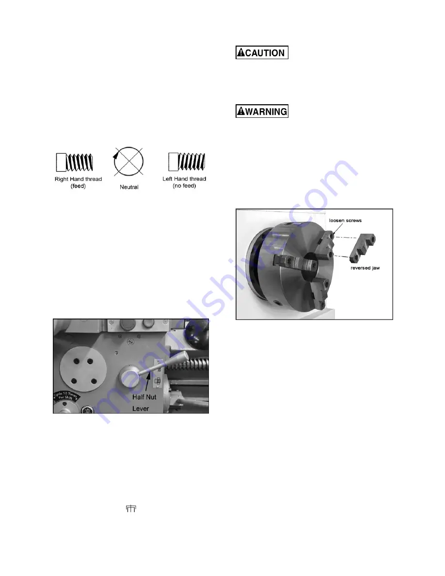
1. Move
thread selection lever
(F, Figure 31) to
desired direction, for right-hand or left-hand
threads.
NOTE: The overrunning clutch in the
apron will prevent the tool post from feeding
for left-hand threads. It will only feed when
right-hand threads are being cut.
Figure 32
2. Set
speed levers
(E
1
,E
2,
Figure 31) to desired
speed. Use the lowest speed possible when
threading.
3. Select desired thread using
thread pitch
levers
(G
1
,G
2
,G
3
, Figure 31) in conjunction
with the charts on the headstock. These charts
are also included in
section 16.10
of this
manual.
4. Engage the half nut (Figure 33). The half nut
must be engaged during the entire threading
process when doing metric, diametral, and
modular threading.
Figure 33
5. When tool reaches end of cut, disengage and
back out the tool to clear the workpiece.
6. Reverse direction to allow cutting tool to return
to its starting point.
7. Repeat the process until desired result is
obtained.
NOTE:
When a special thread must be cut that is
not found on the chart, move thread change control
lever (G
1
, Figure 31) to
position, and lever (G
3
)
to
IV
, then reset the change gears.
13.0
Adjustments
Adjustments to the lathe,
especially those involving alignments of
bearings, spindle, leadscrew, clutch, etc.,
should only be performed by qualified
personnel, as improper alignments can damage
the machine and/or create a safety hazard.
Turn off main switch and press
emergency stop button before making
adjustments to the lathe.
13.1
Chuck Jaw Reversal
The three jaws on the scroll chuck are reversible,
to hold stock with larger diameters. See Figure 34.
Loosen the two screws with the provided hex key,
remove the jaw, and rotate it 180-degrees. Re-
install the jaw, and tighten each screw in
increments until fully tightened.
Figure 34 – Chuck jaw reversal
13.2
Gib Adjustments
After a period of time, some of the moving
components may need adjustment for play due to
wear.
Do not overtighten gib screws as this can
hasten wear to components.
Saddle
– Turn screws (A, Figure 35) on either side
of the saddle at the rear to adjust drag on the
saddle.
Cross Slide
– Gib screws are located at front and
rear of slide opposite to one another (B, Figure 36).
To adjust drag, loosen rear gib screw one turn, and
tighten front gib screw a quarter turn. Rotate the
handwheel to check the play. Repeat as needed
until slide moves freely without play. Gently tighten
rear gib screw.
Summary of Contents for GH-26120ZH
Page 34: ...34 18 0 Change Gear Diagram Figure 54 ...
Page 35: ...35 This page intentionally left blank ...
Page 40: ...4 1 1 Bed Assembly I Exploded View ...
Page 41: ...5 1 2 Bed Assembly I for 120 ZH only Exploded View ...
Page 44: ...8 2 1 Bed Assembly II Exploded View ...
Page 45: ...9 2 2 Bed Assembly II for 120 ZH only Exploded View ...
Page 48: ...12 3 1 Headstock Assembly I Exploded View Ⅲ Ⅳ Ⅴ Ⅶ Ⅵ Ⅱ Ⅰ Ⅱb Ⅶb ZⅡ ZⅠ ZⅡ ...
Page 51: ...15 4 1 Headstock Assembly II Exploded View ...
Page 54: ...18 5 1 Headstock Assembly III Exploded View ...
Page 56: ...20 6 1 Headstock Assembly IV Exploded View Ⅰ Ⅱb Ⅱ Ⅲ Ⅳ Ⅴ ...
Page 59: ...23 7 1 Headstock Assembly V Exploded View Ⅶ Ⅶb Ⅵ ...
Page 62: ...26 9 1 Gear Box Assembly I Exploded View Ⅱ Ⅲ Ⅰ ...
Page 64: ...28 10 1 Gear Box Assembly II Exploded View ...
Page 67: ...31 11 1 Gear Box Assembly III Exploded View ...
Page 70: ...34 12 1 Brake Assembly Exploded View ...
Page 72: ...36 13 1 Saddle and Cross Slide Assembly Exploded View ...
Page 75: ...39 14 1 Tool Post and Compound Rest Assembly Exploded View ...
Page 77: ...41 15 1 Apron Assembly I Exploded View Ⅱ Ⅹ Ⅱ Ⅲ Ⅷ Ⅹ Ⅸ Ⅹ Ⅳ Ⅰ Ⅹ Ⅰ Ⅵ Ⅲ Ⅴ Ⅶ ...
Page 80: ...44 16 1 Apron Assembly II Exploded View Ⅺ Ⅹ Ⅲ Ⅻ Ⅸ Ⅹ Ⅶ ...
Page 83: ...47 17 1 Apron Assembly III Exploded View Ⅰ Ⅱ Ⅴ Ⅲ Ⅳ Ⅵ ...
Page 85: ...49 18 1 Apron Assembly IV Exploded View ...
Page 87: ...51 19 1 Tailstock Assembly I Exploded View ...
Page 89: ...53 20 1 Tailstock Assembly II Exploded View ...
Page 91: ...55 21 1 Steady Rest Assembly Small and Large Exploded View ...
Page 95: ...59 24 1 Travel Stop Assembly Exploded View ...
Page 100: ...64 27 2 Electrical Diagram ...


