30
15.0
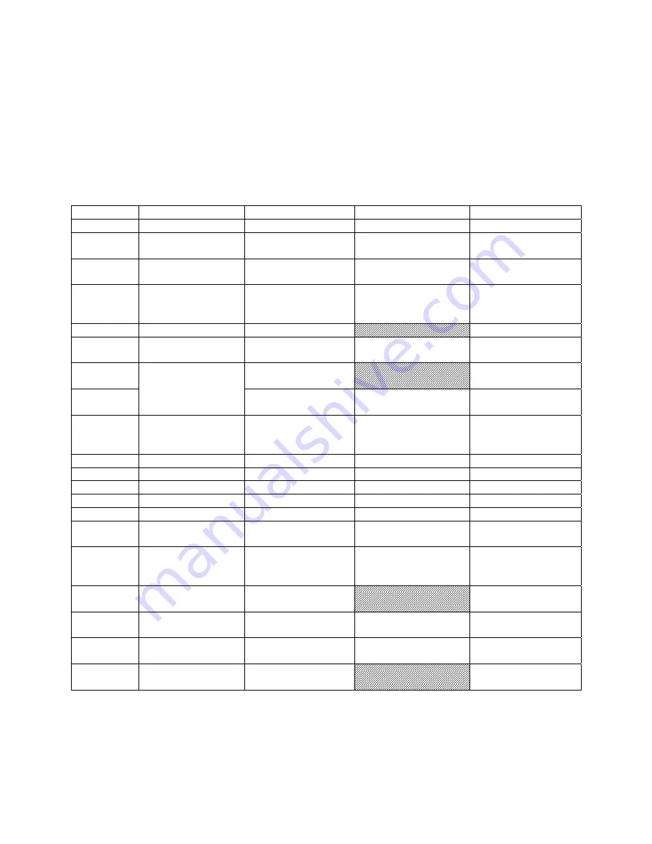
Lubrication Schedule and General Maintenance
Regularly scheduled maintenance is crucial to ensure a long service life for your machine. The schedule below shows
general cleaning, lubrication points and coolant replacement information for the ZH Series Lathes.
Push stop button
and power off before lubricating.
Follow local regulations for disposal of used coolant/lubricants. Minimize direct
skin contact with lubricants and coolants, and wear eye protection when pouring coolant in case of splash.
Mobile DTE® Oil Heavy Medium is recommended for the SAE-20W machine oil.
If the brand of oil is ever changed, it is recommended that you flush and clean the reservoir first to prevent any
compatibility issues.
Table 3
Figure/Sect. Element
Action
Lubricant
Frequency
sect 8.3
Chuck
Grease jaws and scroll
#2 lithium tube grease
periodically
sect 8.3
Spindle/cam
locks/chuck body
light coat of oil
SAE-20W machine oil
periodically
sect 8.2
All exposed metal
surfaces
light coat of oil
SAE-20W machine oil
frequently
Figure 9,10
Headstock
Drain and fill
SAE-20W machine oil
- after first 10 days,
- after next 20 days,
- every 2 to 3 months
Figure 11
Oil filter
Clean
monthly
Figure 9,10
Gearbox
Drain and fill
SAE-20W machine oil
- after first 3 months,
- every 6 months
Figure 12
Apron and Saddle
Activate one shot lube
handle
multiple times per shift,
or as needed
Figure 12
Drain and fill
SAE-20W machine oil
- after first 3 months,
- then annually
Figure 15
Leadscrew; Feed
Rod; Spindle
Direction Control Axle
Fill at oil port
SAE-20W machine oil
as needed
Figure 15
Travel Setting Rod
Fill at (2) ball oilers
SAE-20W machine oil
as needed
Figure 10
Change Gear Axle
grease
#2 lithium tube grease
once every shift
Figure 13
Cross slide
Fill at (2) ball oilers
SAE-20W machine oil
daily
Figure 13
Compound rest
Fill at (3) ball oilers
SAE-20W machine oil
daily
Figure 16
Tailstock
Fill at (2) ball oilers
SAE-20W machine oil
daily
Figure 14,16
Anti-dust felt on v-
ways
Clean kerosene
Inspect
weekly
sect 9.1
Coolant reservoir *
(follow coolant
manufacturer’s
directions)
Coolant of choice,
approx. 4 gallons
(follow coolant
manufacturer’s
directions)
sect 9.1
Chip trays
Clean; clear drain
filters
periodically
Figure 52
Steady Rest
Lubricate finger shafts
and contact points
Lead-based grease
before each use
sect 13.17
Follow Rest
Lubricate finger shafts
and contact points
Lead-based grease
before each use
Figure 42
Belts
Inspect and tighten if
needed
periodically
Summary of Contents for GH-26120ZH
Page 34: ...34 18 0 Change Gear Diagram Figure 54 ...
Page 35: ...35 This page intentionally left blank ...
Page 40: ...4 1 1 Bed Assembly I Exploded View ...
Page 41: ...5 1 2 Bed Assembly I for 120 ZH only Exploded View ...
Page 44: ...8 2 1 Bed Assembly II Exploded View ...
Page 45: ...9 2 2 Bed Assembly II for 120 ZH only Exploded View ...
Page 48: ...12 3 1 Headstock Assembly I Exploded View Ⅲ Ⅳ Ⅴ Ⅶ Ⅵ Ⅱ Ⅰ Ⅱb Ⅶb ZⅡ ZⅠ ZⅡ ...
Page 51: ...15 4 1 Headstock Assembly II Exploded View ...
Page 54: ...18 5 1 Headstock Assembly III Exploded View ...
Page 56: ...20 6 1 Headstock Assembly IV Exploded View Ⅰ Ⅱb Ⅱ Ⅲ Ⅳ Ⅴ ...
Page 59: ...23 7 1 Headstock Assembly V Exploded View Ⅶ Ⅶb Ⅵ ...
Page 62: ...26 9 1 Gear Box Assembly I Exploded View Ⅱ Ⅲ Ⅰ ...
Page 64: ...28 10 1 Gear Box Assembly II Exploded View ...
Page 67: ...31 11 1 Gear Box Assembly III Exploded View ...
Page 70: ...34 12 1 Brake Assembly Exploded View ...
Page 72: ...36 13 1 Saddle and Cross Slide Assembly Exploded View ...
Page 75: ...39 14 1 Tool Post and Compound Rest Assembly Exploded View ...
Page 77: ...41 15 1 Apron Assembly I Exploded View Ⅱ Ⅹ Ⅱ Ⅲ Ⅷ Ⅹ Ⅸ Ⅹ Ⅳ Ⅰ Ⅹ Ⅰ Ⅵ Ⅲ Ⅴ Ⅶ ...
Page 80: ...44 16 1 Apron Assembly II Exploded View Ⅺ Ⅹ Ⅲ Ⅻ Ⅸ Ⅹ Ⅶ ...
Page 83: ...47 17 1 Apron Assembly III Exploded View Ⅰ Ⅱ Ⅴ Ⅲ Ⅳ Ⅵ ...
Page 85: ...49 18 1 Apron Assembly IV Exploded View ...
Page 87: ...51 19 1 Tailstock Assembly I Exploded View ...
Page 89: ...53 20 1 Tailstock Assembly II Exploded View ...
Page 91: ...55 21 1 Steady Rest Assembly Small and Large Exploded View ...
Page 95: ...59 24 1 Travel Stop Assembly Exploded View ...
Page 100: ...64 27 2 Electrical Diagram ...


