background image


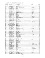
33

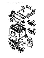
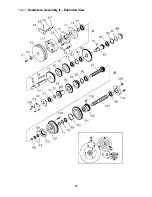
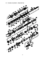
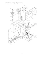
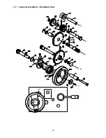
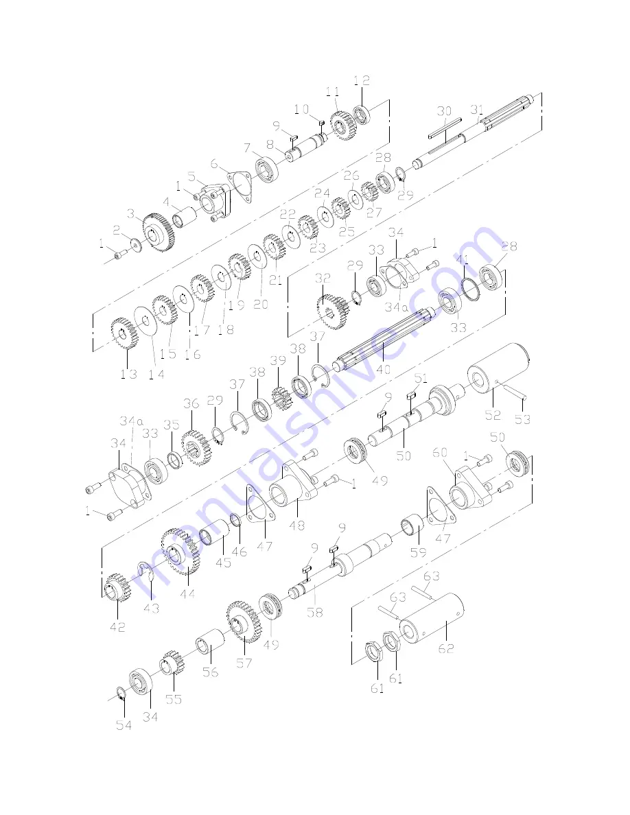
14.5.1

  Gearbox Assembly II – Exploded View 


D

C

B


Summary of Contents for GH-1440

Page 1: ...d Parts Manual Geared Head Lathe 14x40 inch Model GH 1440 JET 427 New Sanford Road LaVergne Tennessee 37086 Part No M 322830 Ph 800 274 6848 Edition 2 12 2017 www jettools com Copyright 2017 JET This pdf document is bookmarked ...

Page 2: ...ay get caught in moving parts Non slip footwear is recommended Wear protective hair covering to contain long hair Do not wear any type of glove 15 Always wear ANSI Z87 1 approved safety glasses or face shield while using this machine Everyday eyeglasses only have impact resistant lenses they are not safety glasses 16 Do not overreach Keep proper footing and balance at all times 17 Do not place han...

Page 3: ...starting the machine 35 Do not operate the lathe in flammable or explosive environments Do not use in a damp environment or expose to rain Familiarize yourself with the following safety notices used in this manual This means that if precautions are not heeded it may result in minor injury and or possible machine damage This means that if precautions are not heeded it may result in serious or even ...

Page 4: ...nd adjustment 21 12 11 Aligning tailstock to headstock 21 13 0 Operation tables 22 13 1 Thread table 22 13 2 Feed table 22 14 0 Replacement Parts 22 14 1 1 Headstock Assembly I Exploded View 23 14 1 2 Headstock Assembly I Parts List 24 14 2 1 Headstock Assembly II Exploded View 26 14 2 2 Headstock Assembly II Parts List 27 14 3 1 Headstock Assembly III Exploded View 28 14 3 2 Headstock Assembly II...

Page 5: ...ration and maintenance procedures for a JET Model GH 1440 Lathe This manual contains instructions on installation safety precautions general operating procedures and maintenance instructions Your machine has been designed and constructed to provide consistent long term operation if used in accordance with the instructions as set forth in this document This manual is not intended to be a training g...

Page 6: ...8 mm Steady rest capacity 1 4 to 3 1 2 in 6 4 to 89 mm Follow rest capacity 1 4 to 2 5 8 in 6 4 to 66 7 mm Headstock Hole through spindle 1 1 2 in 38 mm Spindle nose D1 4 Taper in spindle nose MT5 Spindle taper adaptor MT3 Spindle bearing type Taper roller bearing Number of spindle speeds 12 Range of spindle speeds 40 1800 RPM Gearbox Number of longitudinal and cross feed rates 40 Range of longitu...

Page 7: ...ght approx 2 336 lb 1060 kg 1 subject to local and national electrical codes 2 The specified values are emission levels and are not necessarily to be seen as safe operating levels As workplace conditions vary this information is intended to allow the user to make a better estimation of the hazards and risks involved only L length W width H height TPI threads per inch n a not applicable The specifi...

Page 8: ...ow Rest mounted on lathe 1 6 Three Jaw Chuck w Top Reversing Jaws mounted on lathe 1 8 Four Jaw Chuck with Backplate strapped to container 1 12 Face Plate strapped to container 1 Backplate 1 Tool Box p n GH1440 TBCP Tool Box Contents p n GH1440 TBCP Fig 1 1 No 1 Cross Point Screwdriver 1 No 1 Flat Blade Screwdriver 4 Open End Wrench 9 11 10 12 12 14 17 19mm 7 Hex Socket Wrench 2 2 5 3 4 5 6 8mm 2 ...

Page 9: ...he must be level to be accurate 6 Clean all rust protected surfaces using a mild commercial solvent kerosene or diesel fuel Do not use paint thinner gasoline or lacquer thinner as these can damage painted surfaces Cover all cleaned surfaces with a light film of Mobil DTE Oil Heavy Medium 7 Open the end gear door Clean all components of the end gear assembly and coat all gears with Mobilith AW 1 Cl...

Page 10: ...rication points and all reservoirs filled to operating level before the lathe is put into service Failure to comply may cause serious damage to the lathe 1 Headstock Oil must be up to indicator mark in oil sight glass A Fig 4 Top off with Mobil DTE Oil Heavy Medium Fill by pulling plug D Fig 4 To drain remove drain plug A Fig 5 with an 8mm hex wrench Drain oil completely and refill after the first...

Page 11: ...crew Feed Rod Lubricate ball oiler A Fig 8 on leadscrew feed rod bracket with Mobil DTE Oil Heavy Medium once daily 5 Tailstock Lubricate two ball oilers B Fig 8 on tailstock with Mobil DTE Oil Heavy Medium once daily 6 Cross Slide Lubricate four ball oilers A Fig 9 with Mobil DTE Oil Heavy Medium once daily 7 Compound Rest Lubricate one ball oiler B Fig 9 with Mobil DTE Oil Heavy Medium once dail...

Page 12: ...ove the cover Run the main power through the strain relief bushing and attach the ground followed by power leads Replace the cover Main Power Switch Located on the backside of the machine Turns the power to the machine on and off Make sure the lathe is properly grounded Power is connected properly when pulling up on the forward reverse lever causes spindle to rotate counterclockwise as viewed from...

Page 13: ... C Fig 12 can be rotated through 360 The top slide and the cross slide travel in a dovetail slide and have adjustable gibs A four way tool post is fitted on the top slide Four way tool post The four way toolpost D Fig 12 is mounted on the top slide and allows a maximum of four tools to be mounted simultaneously Remember to use a minimum of two clamping screws when installing a cutting tool Apron T...

Page 14: ...y Medium 4 After prolonged use the fingers will show wear Re mill or file the tips of the fingers Follow rest The traveling follow rest F Fig 13 is mounted on the saddle and follows the movement of the turning tool Only two fingers are required as the place of the third is taken by the turning tool The follow rest is used for tuning operations on long slender workpieces It prevents flexing of the ...

Page 15: ...h the knob in the six o clock position feed lead selector knob J Fig 14 may be adjusted With the knob in the twelve o clock position the feed lead selector knob J Fig 14 is locked 7 Feed Lead Selector Knob J Fig 14 located on front of the gearbox Used for setting up for feeding and threading 8 Compound Lock A Fig 15 hex socket screw located on left side of compound Turn clockwise to lock and count...

Page 16: ...d on the tailstock Rotate clockwise to advance the quill Rotate counter clockwise to retract the quill 19 Tailstock Off Set Adjustment D Fig 16 Two hex socket cap screws located on the tailstock base are used to off set the tailstock for cutting tapers Loosening one screw while tightening the other off sets the tailstock 20 Foot Brake A Fig 17 located between stand pedestals Depress to stop all la...

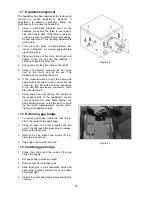
Page 17: ...headstock 3 Loosen nuts A B Fig 19 4 Move quadrant C Fig 19 out of the way and hold in place temporarily by tightening nut B Fig 19 5 Remove hex socket cap screws D and or E Fig 19 depending on which gear is to be changed 6 Install new gear s and tighten in place with a hex socket cap screw 7 Loosen nut B Fig 19 move quadrant back so teeth mesh on gears and tighten nuts A B Fig 19 CAUTION Make sur...

Page 18: ... has been selected and the half nut is initially engaged thread dial cannot be used 11 7 Compound rest The compound rest is located on top of the cross slide and can be rotated 360 degrees Loosen the two socket head cap screws A Fig 22 on the compound rest base There is a calibrated dial in degrees B Fig 22 below the rest to assist in placement of the compound to the desired angle 12 0 Adjustments...

Page 19: ...compound rest Rear gib screw is shown A Fig 23 Front gib screw not shown is by the handwheel 12 4 Tailstock If the handle A Fig 24 will not lock the tailstock follow the procedure below 1 Lower the handle to the unlocked position 2 Slide the tailstock to an area that allows access to the underside of the tailstock 3 Tighten tailstock clamping bolt underside of tailstock 1 4 turn Test for proper lo...

Page 20: ...he same and adjustment is required loosen hex socket cap screws A Fig 25 which hold the headstock to the bed Do not loosen completely some drag should remain 7 Adjust two screw nuts B Fig 25 located on the endgear side of the headstock Loosen one and tighten the other Make another cut Keep adjusting screw nuts after each cut until the bar stock measurements are the same Tighten all headstock screw...

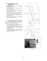
Page 21: ...y 3 4 deflection on belts 6 Close end gear door install cover and connect lathe to the power source 12 11 Aligning tailstock to headstock Before proceeding headstock should be aligned See sect 12 7 Headstock Alignment 1 Fit a 12 ground steel bar between centers of the headstock and tailstock Fig 28 2 Fit a dial indicator to the compound slide and traverse the center line of the bar using the carri...

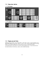
Page 22: ... call 1 800 274 6848 Monday through Friday 8 00 a m to 5 00 p m CST Having the Model Number and Serial Number of your machine available when you call will allow us to serve you quickly and accurately Non proprietary parts such as fasteners can be found at local hardware stores or may be ordered from JET Some parts are shown for reference only and may not be available individually ...

Page 23: ...23 14 1 1 Headstock Assembly I Exploded View ...

Page 24: ...Hd Screw M3x6 14 28 GH1440 04 59 Screw 3 29 TS 1514011 Socket Hd Flat Screw M6x12 6 30 GH1440 04 50 Position Plate 2 31 GH1440K 031 O Ring 19x2 65 mm 3 32 GH1440 04 40 Gear Shaft 22T 1 33 GH1440 04 42 Gear Shaft 17T 1 34 GH1440 04 51 Position Plate 1 35 GH1440 04 58 Lever Hub 1 36 TS 1506051 Hex Socket Hd Cap Screw M12x40 2 37 GB5782 86 Alignment Bolt M10x40 2 38 GH1440 04 62 Alignment Bolt 2 39 G...

Page 25: ...25 Index No Part No Description Size Qty 142 GH1440K 142 O Ring 25x2 65 mm 3 159 TS 1506041 Hex Socket Hd Cap Screw M12x35 2 160 GH1440K 02304 24 Name Plate 1 ...

Page 26: ...26 14 2 1 Headstock Assembly II Exploded View ...

Page 27: ...204 p5 5 83 GH1440 04 17 Washer 1 84 GH1440 04 12 Gear 57T 1 85 GH1440 04 11 Gear Shaft 20T 1 86 F006075 C Retaining Ring Int 47 mm 1 87 GH1440K 287 O Ring 40x2 65 1 88 GH1440K 02106 Plug 1 89 04 53 Bearing Cap 2 90 04 52 Gasket 2 91 GH1440 04 08 Gear 28T 1 92 GHW H92 Key Dbl Rd Hd 8x38 mm 1 93 GH1440 04 09 Gear 41T 1 94 GH1440 04 10 Gear 34T 1 95 F006055 C Retaining Ring Ext 40 mm 1 96 BB 6005 Ba...

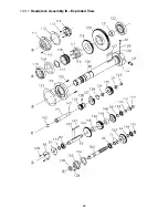
Page 28: ...28 14 3 1 Headstock Assembly III Exploded View ...

Page 29: ...aring 30212 p5 1 123 GH1440 04 32 Gasket 1 124 GH1440 04 28 Cover 1 125 TS 1503061 Hex Socket Hd Cap Screw M6x25 3 126 5509094 Key Dbl Rd Hd 6x30 mm 1 127 GHW H127 Key Dbl Rd Hd 10x55 mm 1 128 JHM610 22 Hex Socket Hd Cap Screw M6x14 6 129 04 31 1 Spring 3 130 04 86 Camlock Set Pin 3 131 04 85 Camlock 3 132 GH1440K 02701 Spindle 1 133 F006047 C Retaining Ring Ext 20 mm 4 134 04 36 Washer 2 135 04 3...

Page 30: ...30 14 4 1 Gearbox Assembly I Exploded View ...

Page 31: ...1 26 05 01 Shift Key 3 27 05 12 Shift Fork 1 28 GH1440 0128 Shaft 1 29 05 15 Shaft 1 29a TS 2276081 Socket Set Screw M6x8 2 30 05 05 Locating Plate 1 31 05 04 Control Plate 1 32 TS 150303 Hex Socket Hd Cap Screw M6x12 4 34 GH1440K 05701 Shift Hub 1 35 6293384 Key Dbl Rd Hd 4x10 mm 3 36 GH1440K 05702 Shaft 1 38 05 14 Gear 26T 1 39 05 55 Shift Fork 1 40 GA7X 122 Spring Pin 5x20 mm 1 41 GHB1340 A82 S...

Page 32: ...32 Index No Part No Description Size Qty 64 GH1440K 05301 19 Name Plate 1 65 GB2672 Screw M3x6 6 66 GH1440K 05303 Graphic Plate Speed Chart 1 ...

Page 33: ...33 14 5 1 Gearbox Assembly II Exploded View D C B ...

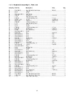
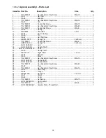
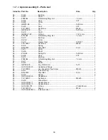
Page 34: ...y Slot Washer 1 25 GH1440K 05707 Gear 18T 1 26 GH1440K 05713 Key Slot Washer 1 27 GH1440K 05706 Gear 16T 1 28 BB 6003 Ball Bearing 6003 P5 2 29 F006047 C Retaining Ring Ext 20 mm 3 30 F014005 Key Dbl Rd Hd 5x5x75 mm 1 31 GH1440A 05733A Shaft Inch 1 32 GH1440A 05721 Gear 16T 32T 1 33 BB 6202 Ball Bearing 6202 p5 3 34 05 47 Flange 2 34a 05 48 Flange 2 35 GH1440A 05118 Shaft Collar 1 36 05 37 Gear 26...

Page 35: ...35 Index No Part No Description Size Qty 58 GH1440K 05705 Shaft 1 59 GH1440A 05307 Shaft Collar 1 60 05 18 Flange 1 61 05 20 Nut 2 62 GH1440K 05726 Collar 1 63 GB117 4x35 Taper Pin 4x35 mm 2 ...

Page 36: ...36 14 6 1 Apron Assembly I Exploded View ...

Page 37: ...11 Socket Set Screw M6x6 1 16 JRD1000 J39 Spring Pin 5x50 mm 1 17 GH1440 06 09 Hub 1 18 GH1440 06 04 Handle Shaft 1 19 GB4141 14 BM10x50 Knob 2 20 06 40 Safety Catch 1 21 GB1160 12 Sight Glass 12 mm 1 22 06 04 Bracket 1 23 06 16 Block 1 24 TS 1503031 Hex Socket Hd Cap Screw M6x12 2 25 GH1440 06 07 Spline Shaft 1 26 GH1440 06 08 Handle Shaft 1 27 TS 1503101 Hex Socket Hd Cap Screw M6x45 3 28 06 02 ...

Page 38: ...38 14 7 1 Apron Assembly II Exploded View A D E C B A B C D E ...

Page 39: ... Set Screw M8x8 1 52 06 14 Spring 1 53 SB 6MM Steel Ball 6 mm 1 54 06 13 Shaft 1 55 06 06 Shaft 1 56 ZX S48 Spring Pin 5x30 mm 1 57 06 08 Gear 50T 1 58 06 10 Bushing 1 59 F006044 C Retaining Ring Ext 16 mm 1 60 06 11 Plug 1 61 06 07 Shaft 1 62 GB1096 79 Key Dbl Rd Hd 5x15 1 63 GH1440 06 05 Handwheel Flange 1 64 TS 150304 Hex Socket Hd Cap Screw M6x16 3 65 06 31 Indicator Ring 1 66 SB 6MM Steel Bal...

Page 40: ...40 14 8 1 Saddle and Cross Slide Assembly Exploded View ...

Page 41: ...mm 1 27 TS 1531012 Pan Head Machine Screw M3x6 2 28 GH1440K 04713 Indicator Plate 1 29 GH1440K 04103 Housing 1 30 TS 1503091 Hex Socket Hd Cap Screw M6x40 2 31 BB 8102 Thrust Bearing 8102 2 32 GH1440A 04715 Washer spcl 1 33 TS 1533032 Pan Head Machine Screw M5x10 2 34 GH1440A 04716A Index Ring 1 35 GH1440A 04107 Compound Handle 1 36 GH1440A 04717 Cover Screw 2 37 TS 1523071 Socket Set Screw M6x25 ...

Page 42: ...42 Index No Part No Description Size Qty 65 GHB1340A 04788 Pin 1 66 GHB1340A 04507 Sleeve 1 67 GH1440K04303 Plate 1 ...

Page 43: ...43 14 9 1 Top Slide and Tool Post Exploded View ...

Page 44: ...16 GH1440A 04724C Compound Screw 1 17 GB1096 79 Key Dbl Rd Hd 4x14 mm 1 18 TS 1531012 Screw M3x6 2 19 GH1440K 04714 Indicator Label 1 20 GH1440A 04110 Screw Bushing 1 21 TS 1503051 Hex Socket Hd Cap Screw M6x20 2 22 BB 8103 Thrust Bearing 8103 1 23 GH1440A 04723A Index Ring 1 24 GH1440A 04109 Handwheel 1 25 GH1440A 04722 Handle 1 26 TS 1502061 Hex Socket Hd Cap Screw M5x25 1 27 GH1440A 04717 Cover...

Page 45: ...45 14 10 1 Tailstock Assembly Exploded View ...

Page 46: ...t Screw M6x30 1 19 GH1440A 06721 Cover Screw 1 20 GH1440A 06720 Handle Lever 1 21 GH1440A 06719 Handle Sleeve 1 22 TS 1504131 Hex Socket Hd Cap Screw M8x70 2 23 GH1440K 03711 Gib 1 24 GH1440K 03712 Gib Adjusting Screw 2 25 TS 1492071 Hex Cap Bolt M12x70 1 26 TS 155008 Washer 12 mm 1 27 GH1440K 03103 Tailstock Clamp Plate 1 28 GH1440A 03710 Block 1 29 GH1440K 03104 Tailstock Base 1 30 F012319 Hex J...

Page 47: ...47 14 11 1 Bed and Shaft Assembly Exploded View ...

Page 48: ... Socket Set Screw M8x10 2 24 GH1440A 01718 Collar 1 25 GH1440K 01701 Control Rod 1 26 ZX S41 Spring Pin 5x40 mm 1 27 GH1440A 01706 Clutch 1 28 SB 6MM Steel Ball 6 mm 3 29 TS 152402 Socket Set Screw M8x10 2 30 01 38 Spring 1 2 6 28 mm 2 31 GH1440A 01711 Sleeve 1 32 SP 36 Spring Pin 3x6 mm 2 33 F014006 Key Dbl Rd Hd 5x36 mm 1 34 TS 1524011 Socket Set Screw M8x8 1 35 GB2089 80 Spring 0 8x5x25 mm 1 36...

Page 49: ...49 Index No Part No Description Size Qty 58 F010448 Socket Set Screw DP M8x16 1 59 C0632A 01504 Shaft Box Cover 1 60 TS 1502021 Socket Head Cap Screw M5x10 4 ...

Page 50: ...50 14 12 1 Stand and Brake Assembly Exploded View ...

Page 51: ...22 GH1440K 01708 Cover 1 23 TS 1503061 Hex Socket Hd Cap Screw M6x25 2 24 TS 1550041 Flat Washer 6 mm 2 25 TS 1503071 Hex Socket Hd Cap Screw M6x30 1 26 GH1440K 22703 Angle Steel M12 1 27 TS 2311061 Hex Nut M6 1 28 TS 1524021 Socket Set Screw M8x10 1 29 GH1440A 22705 Link Nut 1 30 TS 2311061 Hex Nut M6 1 31 GH1440A 22713 Screw 1 32 ESR1650 18 Spring Pin 5x40mm 1 33 GH1440A 22101 Link 1 34 GH1440A ...

Page 52: ...52 14 13 1 End Gear Assembly Exploded View ...

Page 53: ... 6mm 1 18 05 41 Gear 50T 1 19 GB1096 5X14 Key Dbl Rd Hd 5x14 mm 1 20 TS 1504041 Hex Socket Hd Cap Screw M8x20 4 21 ZX H218 Pin 6x25 mm 2 22 GH1440K 05722 Bracket 1 23 TS 1550061 Flat Washer 8mm 2 24 TS 1504041 Hex Socket Hd Cap Screw M8x20 2 25 PS1652T 105 Phillips Pan Hd Machine Screw M4x40 2 26 QKS8 1 Door Switch 1 ZH SQ1 Door Switch Assembly includes 26 32 1 27 C0632A 18704 Bracket 1 28 TS 1550...

Page 54: ... FRA Follow Rest Assembly 1 thru 10 1 GH1440 09 02 Knob 2 2 TS 1523011 Socket Set Screw M6x6 2 3 10B 04 Bushing 2 4 10B 05 Screw 2 5 10B 02 Sleeve 2 6 10B 06 Brass Finger 1 7 TS 2311061 Hex Nut M6 2 8 TS 1523011 Socket Set Screw M6x6 2 9 GH1440 09 01 Follow Rest Body 1 10 TS 1503101 Hex Socket Hd Cap Screw M6x45 2 ...

Page 55: ...iption Size Qty GH1440K TDA Thead Dial Assembly includes 1 thru 9 1 06 22 Dial 1 2 GB879 3x12 Spring Pin 3x12 1 3 06 23 Shaft 1 4 GB879 3x20 Spring Pin 3x20 1 5 06 25 Gear 32T 1 6 06 24 Body 1 7 TS 1503101 Hex Socket Hd Cap Screw M6x45 1 8 GH1440K 11305 1 Graphic Plate Thread Dial 1 9 TS 1531012 Screw M3x6 4 ...

Page 56: ...56 14 16 1 Steady Rest Parts List ...

Page 57: ... 03 Steady Rest Upper Body 1 8 F004047 Dowel Pin 8x40 mm 1 9 TS 1523061 Socket Set Screw M6x20 3 10 TS 1540041 Hex Nut M6 3 11 GH1440 10 01 Steady Rest Lower Body 1 12 10A 02 Lock Pin 1 13 TS 1540081 Hex Nut M12 1 14 TS 1550081 Washer 12 mm 1 15 GH1440 10 02 Clamp Plate 1 16 TS 1550081 Flat Washer 12 mm 1 17 TS 1492081 Hex Cap Bolt M12x80 1 18 GH1440K 1618 Knurled Thumb Knob 1 19 GH1440K 1619 Pivo...

Page 58: ...cket Hd Cap Screw M6x20 3 3 TS 1502051 Hex Socket Hd Cap Screw M5x20 3 4 GH1440K 1704 Coolant Nozzle C2 77 3 5 TS 1503041 Hex Socket Hd Cap Screw M6x16 1 6 GHB1440A01739 Rubber Tube 1 7 TS 1482011 Hex Cap Bolt M6x10 4 8 YSB 12TH Coolant Pump 3PH 1 YDB 12TH Coolant Pump 1PH 1 9 TS 1550041 Flat Washer 6 mm 4 10 GH1440K01715 Coolant Tank 1 11 GH1440K1711 Tube 600 mm 1 12 GH1440K18711 Support 1 ...

Page 59: ...Cap Screw M6x12 2 6 TS 1540041 Hex Nut M6 2 7 TS 1540021 Hex Nut M4 4 8 TS 1550021 Plain Washer 4 mm 8 9 TS 1532042 Cross Recessed Pan Head Screw M4x12 4 10 TS 1550041 Plain Washer 6 mm 3 11 TS 1534032 Cross Recessed Pan Head Screw M6x10 3 12 GH1440K 19702J Rest Bar 1 13 TS 1524021 Hex Socket Set Screw M8x10 2 14 TS 1503071 Hex Socket Hd Cap Screw M6x30 3 15 TS 1524041 Hex Socket Set Screw M8x16 1...

Page 60: ...H1440K 14701 Left Flange 1 2 TS 1502031 Hex Socket Hd Cap Screw M5x12 2 3 LGB 28 900 70 Telescoping Sleeve 2 4 TS 2285121 Phillips Flat Head Machine Screw M5x12 8 5 GH1440A 14702 Cover 2 6 GH1440K 14702 Left Flange Bracket 1 7 TS 1503041 Hex Socket Hd Cap Screw M6x16 4 8 GH1440K 14101 Right Flange Bracket 1 9 GH1440A 14703 Right Flange 1 ...

Page 61: ...61 14 20 1 Accessories I Exploded View ...

Page 62: ... 1 11 GH1440 06 11 Live Center MT 3 1 12 C0632 09701 Tapered Reducing Sleeve No 5 to No 3 1 13 1440R F001 Drift Key 1 14 GH1440B 1707 Oil Gun 1 15 Touchup Paint Can Gray 1 16 C0632 04726 Tool Post Wrench Rod 1 C0632 04727 Tool Post Wrench 1 17 C0632 09705 Cam Lock Key Rod 1 C0632 09704 Cam Lock Key 1 18 GH1440 0618 Chuck Key 1 19 GH1340A TBCP 16 03 Open End Wrench 9 11mm 1 20 6295506 Open End Wren...

Page 63: ... Parts List Index No Part No Description Size Qty 1 K72200D4 Four Jaw Chuck with Camlock Stud 8 1 2 K11160AD4 Three Jaw Chuck with Camlock Stud Direct Mount 6 1 3 C0632 09101 Face Plate 12 1 4 C0632 02722 Camlock Stud 3 5 TS 1503021 Hex Socket Hd Cap Screw M6X10 3 ...

Page 64: ...Relay LR2 D1321N 1 8 GH1440K FR2 FR2 Motor Overload Relay LR2 D1304N 1 9 GH1440K TC TC Transformer JBK5 100TH 1 10 GH1440K SQ2 SQ2 Door Switch QKS8 1 11 GH1440K QS1 QS1 Power On Off Switch VCD0 1 12 GH1440K SQ1 SQ1 Brake Switch TM 1701 1 13 GH1440K SB1 SB1 Off Switch ZB2 BS54C 1 14 GH1440K SB2 SB2 Jog Switch ZB2BA3C 1 15 GH1440K HL HL Power Indicator Light XB7 EVF3LC 1 16 GH1440K SA2 SA2 Coolant P...

Page 65: ...65 15 0 Electrical Connections 15 1 Wiring Diagram 1 Phase ...

Page 66: ...66 15 2 Wiring Diagram 3 Phase ...

Page 67: ...needed JET has Authorized Service Centers located throughout the United States For the name of an Authorized Service Center in your area call 1 800 274 6846 or use the Service Center Locator on the JET website More Information JET is constantly adding new products For complete up to date product information check with your local distributor or visit the JET website How State Law Applies This warra...

Page 68: ...68 427 New Sanford Road LaVergne Tennessee 37086 Phone 800 274 6848 www jettools com ...

Reviews: