13
10.0
General description
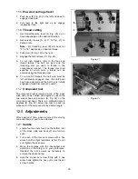
Lathe bed
The lathe bed (A, Fig. 11) is made of high grade
cast iron. By combining high cheeks with strong
cross ribs, a bed with low vibration and high rigidity
is realized. Two precision ground v-slideways,
reinforced by heat hardening and grinding, are an
accurate guide for the carriage and headstock. The
main drive motor is mounted in the stand below
headstock.
Headstock
The headstock (B, Fig. 11) is cast from high grade,
low vibration cast iron. It is bolted to the bed by
four screws with two adjusting screws for
alignment. In the head, the spindle is mounted on
two precision taper roller bearings. The hollow
spindle has Morse Taper #5 with a 1-1/2" bore.
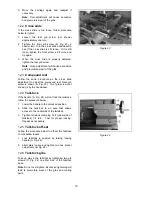
Carriage
The carriage (A, Fig. 12) is made from high quality
cast iron. The sliding parts are smooth ground. The
cross slide is mounted on the carriage and moves
on a dovetailed slide which can be adjusted for
play by means of the gibs.
The compound slide (B, Fig. 12), which is mounted
on the cross slide (C, Fig. 12), can be rotated
through 360
°
. The top slide and the cross slide
travel in a dovetail slide and have adjustable gibs.
A four way tool post is fitted on the top slide.
Four way tool post
The four way toolpost (D, Fig. 12) is mounted on
the top slide and allows a maximum of four tools to
be mounted simultaneously. Remember to use a
minimum of two clamping screws when installing a
cutting tool.
Apron
The apron (E, Fig. 12) is mounted to the carriage.
In the apron a half nut is fitted. The half nut gibs
can be adjusted from the outside. The half nut is
engaged by use of a lever. Quick travel of the
apron is accomplished by means of a bed-
mounted rack and pinion, operated by a
handwheel on the front of the apron.
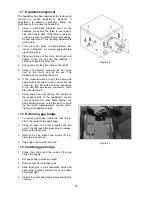
Tailstock
The tailstock (A, Fig. 13) slides on a v-way and can
be locked at any location by a clamping lever. The
tailstock has a heavy duty spindle with a Morse
Taper #3.
Leadscrew and feed Rod
The leadscrew (B, Fig. 13) and feed rod (C, Fig.
13) are mounted on the front of the machine bed.
They are connected to the gearbox at the left for
automatic feed and lead, and are supported by
bushings on both ends. Both are equipped with
brass shear pins.
Figure 11
Figure 12
Figure 13
Summary of Contents for GH-1440
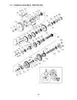
Page 23: ...23 14 1 1 Headstock Assembly I Exploded View ...
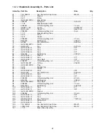
Page 26: ...26 14 2 1 Headstock Assembly II Exploded View ...
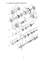
Page 28: ...28 14 3 1 Headstock Assembly III Exploded View ...
Page 30: ...30 14 4 1 Gearbox Assembly I Exploded View ...
Page 33: ...33 14 5 1 Gearbox Assembly II Exploded View D C B ...
Page 36: ...36 14 6 1 Apron Assembly I Exploded View ...
Page 38: ...38 14 7 1 Apron Assembly II Exploded View A D E C B A B C D E ...
Page 40: ...40 14 8 1 Saddle and Cross Slide Assembly Exploded View ...
Page 43: ...43 14 9 1 Top Slide and Tool Post Exploded View ...
Page 45: ...45 14 10 1 Tailstock Assembly Exploded View ...
Page 47: ...47 14 11 1 Bed and Shaft Assembly Exploded View ...
Page 50: ...50 14 12 1 Stand and Brake Assembly Exploded View ...
Page 52: ...52 14 13 1 End Gear Assembly Exploded View ...
Page 56: ...56 14 16 1 Steady Rest Parts List ...
Page 61: ...61 14 20 1 Accessories I Exploded View ...
Page 65: ...65 15 0 Electrical Connections 15 1 Wiring Diagram 1 Phase ...
Page 66: ...66 15 2 Wiring Diagram 3 Phase ...
Page 68: ...68 427 New Sanford Road LaVergne Tennessee 37086 Phone 800 274 6848 www jettools com ...


