16
Adjusting Fence Squareness
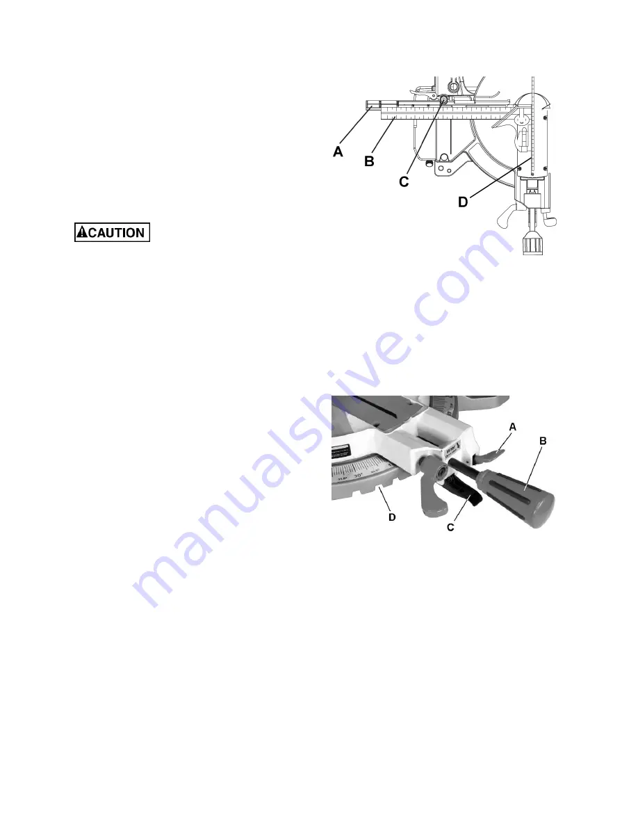
Referring to Figure 11:
1. Loosen
two
fence locking screws
(C).
Note:
One locking screw is located on each fence.
2. Lower the cutting arm and lock in position.
3. Using a
square
(B), lay the heel of the square
against the
blade
(D) and the ruler against the
fence
(A).
4. Adjust the fence 90° to the blade and tighten
the two
fence locking screws
(C).
If the saw has not been used
recently, recheck blade squareness to the fence
and readjust if needed.
5. After fence has been aligned, using a scrap
piece of wood, make a cut at 90º then check
squareness on the piece. Readjust if
necessary.
Positive Stop Miter Angle Adjustment
Referring to Figure 12:
1. Unlock the miter table by lifting up on the quick-
cam
miter table lock
(A).
2. Raise
the
positive stop locking lever
(C) up; at the
same time grasp the
miter handle
(B) and rotate
the miter table left or right to the desired angle.
3. Release
the
positive stop locking lever
(C) and
set the miter at the desired angle making sure
the lever snaps into place.
Note:
There are nine positive stops into which the
lever will lock.
4. After the angle is selected, press down on the
quick-cam
miter table lock
(A).
Quick-cam Miter Table Lock Operation
If a miter angle required is not one of nine positive
stops, the miter table can be locked at any angle
between these positive stops by using the quick-
cam miter table lock.
Referring to Figure 12:
1. Unlock the miter table by lifting up on the quick-
cam
miter table lock
(A).
2. Raise the
positive stop locking lever
(C) up; at
the same time grasp the
miter handle
(B) and
rotate the miter table left or right to the desired
angle.
Figure 11
Figure 12
3. Release the positive stop locking lever (C).
4. Press down on the quick-cam
miter table lock
(A) until it locks the miter table in place.
Note:
The quick-cam miter table lock should lock
the table and prevent it from moving. If adjustment
is needed, see
Quick-cam Miter Table Lock
Adjustment
on following page.
Summary of Contents for Bench JMS-10CMS
Page 9: ...9 Features...
Page 30: ...30 Assembly Drawing...
Page 31: ...31 Assembly Drawing continued...
Page 32: ...32 Assembly Drawing continued...
Page 33: ...33 Wiring Diagram...
Page 34: ...34 Notes...
Page 35: ...35 Notes...


