14
Adjustments
Before attempting any adjust-
ments, make sure the trigger is released and
remove the power cord from the power source
to avoid injury from unexpected starting or
electrical shock. Failure to comply may cause
serious injury!
Note:
Your miter saw was adjusted at the factory.
However, during shipment slight misalignment may
have occurred. Check the following settings and
adjust if necessary prior to using this miter saw.
Bevel Stop Adjustments
To avoid injury from
unexpected starting or electrical shock, make
sure the trigger is released and remove the
power cord from the power source.
90°(0°) Bevel Adjustment
1. Set the miter angle to 0° (see
Miter Angle
on
page 15).
Note:
A
bevel
angle of 0° corresponds to a
blade-
to-miter-table
angle of 90°.
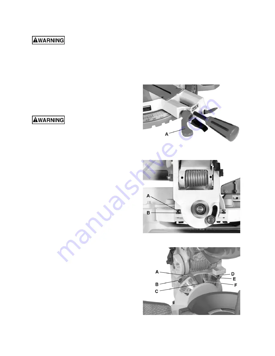
2. Turn
the
bevel lock handle
(A, Fig. 6) clockwise
to loosen and tilt the cutting arm to the 0° bevel
angle. Turn the
bevel lock handle
(A)
counterclockwise to tighten.
3. Place a combination square on the miter table
with the rule against the table and heel of the
square against the saw blade.
If the blade is not 90° to the miter table:
4. To adjust, tilt the cutting arm to 45°, loosen the
lock nut
(B, Fig. 7) and turn the
stop bolt
(A,) in
or out accordingly.
5. Tilt the cutting arm back to the right and
recheck alignment.
6. Repeat steps 1–4 if necessary until the blade is
90° to the table, then tighten the
lock nut
(B,
Fig. 7) to secure the
stop bolt
(A, Fig. 7).
Bevel Scale Indicators
1. Set the blade to be exactly 90°(0°) to the table.
2. With cross-point screwdriver, loosen two
bevel
indicator screws
(B, D, Fig. 8).
3. Adjust
bevel indicators
(A, E, Fig. 8) to the
“0”
marks
(C, F, Fig. 8)
on the bevel scale and
retighten the
screws
(B, D).
Figure 6
Figure 7
Figure 8
Summary of Contents for Bench JMS-10CMS
Page 9: ...9 Features...
Page 30: ...30 Assembly Drawing...
Page 31: ...31 Assembly Drawing continued...
Page 32: ...32 Assembly Drawing continued...
Page 33: ...33 Wiring Diagram...
Page 34: ...34 Notes...
Page 35: ...35 Notes...


