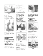
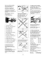
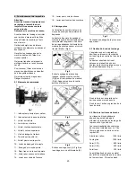
Jet BD-920W Operating Instructions Manual Download Page 7


Fig 20 


The follow rest


is mounted on the saddle and 
follows the movement of the tool. It 
prevents flexing of long and thin 
work pieces under pressure from the 
tool (Fig 21). 


Fig 21 

Set the fingers snug but not overly 
tight. Lubricate the fingers to prevent 
premature wear. 


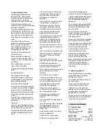
8. Maintenance and inspection 

General notes:  
Maintenance, cleaning and repair 
work may only be carried out after 
the machine is protected against 
accidental starting by pulling the 
mains plug. 

Clean the machine regularly. 

Defective safety devices must be 
replaced immediately. 

Repair and maintenance work on the 
electrical system may only be 
carried out by a qualified electrician. 


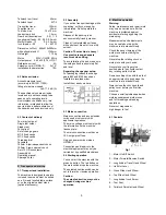
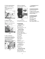
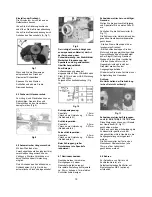
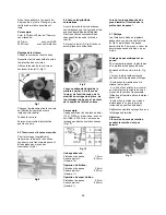
8.1 Lubrication schedule 

Refer to Fig 22 and Fig 23. 

Weekly apply oil to: 

1…oil ball on gear hub 

3…teeth of reversing gear lightly 

4…bed ways lightly 

6…lead screw on entire length 

7…oil ball on lead screw bracket 

8…screw and guides of top slide 

9…oil ball on tailstock body 

10..oil ball on top of carriage 

12..hub of feed lever 

13..oil balls on apron front 

Weekly apply grease to: 

2…teeth of change gears 

5…rack over entire length 

11..tailstock quill over entire length 


Fig 22 


Fig 23 


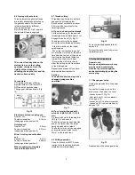
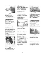
8.2 Bearing adjustment 

The main spindle taper roller 
bearings are adjusted at the factory. 
If end play becomes evident after 
considerable use the bearings may 
be adjusted. 

Loosen set screw (1, Fig 24) in the 
slotted nut (2) on the back of the 
spindle.  


Fig 24 

Tighten nut carefully, the spindle 
should still revolve freely. Excessive 
preloading will damage the bearings. 

Tighten set screw. 


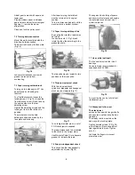
8.3 Cross and top slide 

adjustment 

Each slide is fitted with a gib strip 
and can be adjusted with screws (1, 
Fig 25) fitted with lock nuts (2). 


Fig 25 

Adjust until slides moves freely 
without play. 


8.4 Cross slide spindle  
      adjustment 

Remove the top slide and adjust the 
grub screw (1, Fig 26) until the 
backlash between the spindle and 
the nut is eliminated. 


Fig 26 


Summary of Contents for BD-920W

Page 1: ...carelessness accidental damage repair inadequate maintenance or cleaning and normal wear and tear Guarantee and or warranty claims must be made within twelve months from the date of purchase date of i...

Page 2: ...the machine Remove the chuck key and wrenches before machine operation Specifications regarding the maximum or minimum size of the work piece must be observed Do not remove chips and work piece parts...

Page 3: ...e bed make sure the setup surface is absolutely flat and level Regarding change gear setup For packaging reason the change gears 60 and 120 have been installed in reversed order Install them as shown...

Page 4: ...ur way tool post Avoid big tool extensions 6 4 Spindle speeds selection The correct spindle speed depends on the type of machining the cutting diameter the material to be machined and the cutting tool...

Page 5: ...ading process Start the machine at the lowest spindle speed When the tool reaches the end of cut stop the motor and at the same time back the tool out of the part so that it clears the thread Attentio...

Page 6: ...rs may be turned Loosen two nuts 1 Fig 16 and rotate the top slide according to the graduated scale Fig 16 The top slide may be located in two positions on the cross slide 7 5 Three jaw universal chuc...

Page 7: ...l ball on lead screw bracket 8 screw and guides of top slide 9 oil ball on tailstock body 10 oil ball on top of carriage 12 hub of feed lever 13 oil balls on apron front Weekly apply grease to 2 teeth...

Page 8: ...ician Machine vibration Unbalanced work piece Reduce spindle speed Work piece deflection improve chucking length or diameter support on tailstock end Tool deflection reduce tool length Slide backlash...

Page 9: ...rial und Fertigungsfehlern ist Diese Garantie trifft nicht auf jene Defekte zu welche auf direkten oder indirekten nicht fachgerechten Gebrauch Unachtsamkeit Unfallschaden Reparatur mangelhafte Wartun...

Page 10: ...und Drogen an der Maschine Beachten Sie dass auch Medikamente Einfluss auf Ihr Verhalten nehmen k nnen Halten Sie Unbeteiligte insbesondere Kinder vom Gefahrenbereich fern Die laufende Maschine nie u...

Page 11: ...folgen werkstatt bliche Bedingungen sind dabei ausreichend Die Maschine kann sowohl auf einen ebenen und belastungsf higen Tisch als auch auf den Originalunterschrank Zubeh r festgeschraubt werden 5 2...

Page 12: ...t Reitstock oder L netten ab Fig 3 Fig 4 Vermeiden Sie kurze Einspannl ngen A Fig 5 oder das Spannen auf einem kleinen Durchmesser B Fig 5 Sorgen Sie f r eine stirnseitige Anlage des Werkst cks 6 3 Ei...

Page 13: ...ntiefe 0 2mm Vorschub pro Umdrehung 0 04mm Getriebestufe I Beim Schruppen gro er Durchmesser die Spantiefe reduzieren 6 7 Gewindeschneiden Gewinde werden in mehreren Durchg ngen mit einem Gewindeforms...

Page 14: ...t mittels Aufspannscheibe und Mitnehmerbolzen Fig 14 Fig 14 Schmieren Sie die Reitstock K rnerspitze um ein Verreiben zu verhindern 7 3 Konusdrehen mit Reitstock Bis zu einem Seitenwinkel von 5 k nnen...

Page 15: ...emmen Die Sechskantmuttern 1 festziehen W hrend des Laufens die Gleitbacken gut schmieren Fig 20 Laufl nette Die Mitlaufl nette wird auf den L ngsschlitten aufgesetzt und macht so die Bewegung des Dre...

Page 16: ...ie abgebildet wegkurbeln Den Gewindering 1 Fig 27 nachstellen bis die Spindel in der Mutter wieder spielfrei eingreift Fig 27 8 6 Spindellager Nachstellung L sen Sie den Gewindestift 1 Fig 28 Die Mutt...

Page 17: ...hl reduzieren Werkzeugschneide verschlissen Werkzeug sch rfen Maschine dreht konisch Reitstock ist seitlich versetzt Reitstock ausrichten Maschinenbett ist verdreht Aufspannfl chen m ssen eben sein Ke...

Page 18: ...1 Accessoires 1 D claration de conformit Nous d clarons de notre propre responsabilit que ce produit correspond en tout point aux lignes directives d crites la page 2 Lors de la construction les norme...

Page 19: ...Placer la machine sur un sol stable et plat S assurer que le c ble d alimentation ne g ne pas le travail ni ne risque de faire tr bucher l op rateur Retirer toute pi ce encombrante de la zone de trav...

Page 20: ...e mobile Jeu roues de rechange Pointe fixe CM 2 Pointe fixe CM 3 Comparateur pour filetages Plaques de fixation Mandrin 4 mors 180mm Mandrin universel 3 mors 100 mm Jeu de 3 mors de serrage ext rieur...

Page 21: ...du nombre de tours du moyen de serrage n ose jamais tre d pass e La denture des mors de serrage et celle de la spirale doivent toujours tre compl tement engren es Les mors de serrage d passant le dia...

Page 22: ...profondeur de passe et du choix de la qualit de l tat de surface Par exemple Usinage ext rieur d une pi ce en acier C15 20mm bien serr e avec un outil HSS 350 l min Les roues de rechange suivantes son...

Page 23: ...ous enl verez ensuite Fermez et verrouillez la protection pour la courroie 7 2 Tournage entre les pointes Fixez le toc sur la pi ce et serrez la entre les pointes L entrainement est fait par le platea...

Page 24: ...pans 1 Pendant le tournage bien huiler les mors lisses Fig 20 Lunette suivre La lunette suivre est fix e sur le tra nard et effectue le m me mouvement que le burin Elle vite que les pi ces longues et...

Page 25: ...vis tourne nouveau sans jeu dans l crou Fig 26 8 5 R glage de la vis sup rieure D vissez le palier porte vis comme indiqu sur l image R glez la bague filet e 1 Fig 27 jusqu ce que la vis tourne nouve...

Page 26: ...forte R duire la profondeur de passe ou l avancement Outils surchauff s Vitesse de coupe trop haute R duire la vitesse Outil mouss Aiguiser l outil Machine tourne coniquement Contre pointe d plac e la...

Reviews: