background image


Warranty and Service 

JET warrants every product it sells against manufacturers’ defects. If one of our tools needs service or repair, please 
contact


Technical Service by calling 1-800-274-6846, 8AM to 5PM CST, Monday through Friday. 

Warranty Period


The general warranty lasts for the time period specified in the literature included with your product or on the official 
JET branded website.  


JET products carry a limited warranty which varies in duration based upon the product. (See chart below) 


Accessories carry a limited warranty of one year from the date of receipt. 


Consumable items are defined as expendable parts or accessories expected to become inoperable within a 
reasonable amount of use and are covered by a 90 day limited warranty against manufacturer’s defects. 

Who is Covered 

This warranty covers only the initial purchaser of the product from the date of delivery. 

What is Covered 

This warranty covers any defects in workmanship or materials subject to the limitations stated below. This warranty 
does not cover failures due directly or indirectly to misuse, abuse, negligence or accidents, normal wear-and-tear, 
improper repair, alterations or lack of maintenance. JET woodworking machinery is designed to be used with Wood. 
Use of these machines in the processing of metal, plastics, or other materials outside recommended guidelines may 
void the warranty. The exceptions are acrylics and other natural items that are made specifically for wood turning. 

Warranty Limitations 

Woodworking products with a Five Year Warranty that are used for commercial or industrial purposes default to a 
Two Year Warranty. Please contact Technical Service at 1-800-274-6846 for further clarification.


How to Get Technical Support 

Please contact Technical Service by calling 1-800-274-6846. 

Please note that you will be asked to provide proof 

of initial purchase when calling. 

If a product requires further inspection, the Technical Service representative will 

explain and assist with any additional action needed.


JET has Authorized Service Centers located throughout the 

United States. For the name of an Authorized Service Center in your area call 1-800-274-6846 or use the Service 
Center Locator on the JET website.


More Information 

JET is constantly adding new products. For complete, up-to-date product information, check with your local distributor 
or visit the JET website. 

How State Law Applies 

This warranty gives you specific legal rights, subject to applicable state law.  

Limitations on This Warranty 

JET LIMITS ALL IMPLIED WARRANTIES TO THE PERIOD OF THE LIMITED WARRANTY FOR EACH PRODUCT. 
EXCEPT AS STATED HEREIN, ANY IMPLIED WARRANTIES OF MERCHANTABILITY AND FITNESS FOR A 
PARTICULAR PURPOSE ARE EXCLUDED. SOME STATES DO NOT ALLOW LIMITATIONS ON HOW LONG AN 
IMPLIED WARRANTY LASTS, SO THE ABOVE LIMITATION MAY NOT APPLY TO YOU. 
 
JET SHALL IN NO EVENT BE LIABLE FOR DEATH, INJURIES TO PERSONS OR PROPERTY, OR FOR 
INCIDENTAL, CONTINGENT, SPECIAL, OR CONSEQUENTIAL DAMAGES ARISING FROM THE USE OF OUR 
PRODUCTS. SOME STATES DO NOT ALLOW THE EXCLUSION OR LIMITATION OF INCIDENTAL OR 
CONSEQUENTIAL DAMAGES, SO THE ABOVE LIMITATION OR EXCLUSION MAY NOT APPLY TO YOU. 
 
JET sells through distributors only. The specifications listed in JET printed materials and on official JET website are 
given as general information and are not binding. JET reserves the right to effect at any time, without prior notice, 
those alterations to parts, fittings, and accessory equipment which they may deem necessary for any reason 
whatsoever. JET

®

 branded products are not sold in Canada by JPW Industries, Inc. 

Product Listing with Warranty Period  

90 Days – Parts; Consumable items 
1 Year – Motors; Machine Accessories 
2 Year – Metalworking Machinery; Electric Hoists, Electric Hoist Accessories; Woodworking Machinery used 
for industrial or commercial purposes 
5 Year – Woodworking Machinery 
Limited Lifetime – JET Parallel clamps; VOLT Series Electric Hoists; Manual Hoists; Manual Hoist   
Accessories; Shop Tools; Warehouse & Dock products; Hand Tools; Air Tools 

 
NOTE:  JET is a division of JPW Industries, Inc. References in this document to JET also apply to JPW Industries, 
Inc., or any of its successors in interest to the JET brand. 

Summary of Contents for 708928Z

Page 1: ...Owner s Manual XACTA Fence II Homeshop 30 52 JET 427 New Sanford Road LaVergne Tennessee 37086 Part No M 708928Z Ph 800 274 6848 Revision D1 03 2019 www jettools com Copyright 2015 JET ...

Page 2: ...onal action needed JET has Authorized Service Centers located throughout the United States For the name of an Authorized Service Center in your area call 1 800 274 6846 or use the Service Center Locator on the JET website More Information JET is constantly adding new products For complete up to date product information check with your local distributor or visit the JET website How State Law Applie...

Page 3: ...djustment 11 90 to the Table Adjustment 12 Cursor Adjustment 12 Rail Installation on a non JET Table Saw 12 Trouble Shooting for XACTA Fence II Homeshop 30 52 12 Parts 13 Ordering Replacement Parts 13 Parts for XACTA Fence II Homeshop 30 52 Fence Assembly 13 Parts for XACTA Fence II Homeshop 30 52 Rail Assembly 14 Parts for the XACTA Fence II Homeshop 30 52 Leg Assembly 15 The specifications in th...

Page 4: ...ing keys and wrenches Form a habit of checking to see that keys and adjusting wrenches are removed from the machine before turning it on 14 Keep safety guards in place at all times when the machine is in use If removed for maintenance purposes use extreme caution and replace the guards immediately 15 Make sure the Table Saw is firmly secured to the floor or bench before use 16 Check damaged parts ...

Page 5: ...r possible machine damage This means that if precautions are not heeded it may result in serious injury or possibly even death WARNING Drilling sawing sanding or machining wood products generates wood dust and other substances known to the State of California to cause cancer Avoid inhaling dust generated from wood products or use a dust mask or other safeguards for personal protection Wood product...

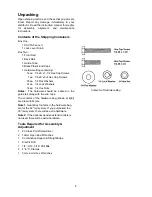
Page 6: ... 1 4 Flat Washers 00021 ea 1 4 Lock Washers 00014 ea 1 4 Hex Nuts Notes The hardware should be packed in the guide rail along with the end caps The contents of the hardware bag shown at right are drawn full scale Note 1 Quantities for items in the hardware bag are for the 52 rail system If you purchased the 30 rail system there will be extra hardware Note 2 If the optional wooden extension table i...

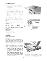
Page 7: ...on the front rail to the four holes in the front edge of the saw table Figure 1 Referring to Figure 2 4 Lightly secure the front rail to the saw table and extension wings with four 1 4 20 x 1 1 2 hex cap screws eight 1 4 flat washers four 1 4 lock washers and four 1 4 hex nuts Tighten just enough to hold the rail next to the table but keep loose enough to allow height adjustment The front rail mus...

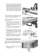
Page 8: ...ension table is an optional accessory Tools required Electric drill Cross point screwdriver 10mm open end wrenches Four clamps Straight edge Hammer or rubber mallet Installation The optional wood extension table including the optional router table sits flush against the saw table and along the inside of the rails The Warning label on the router table should face outward The extension table is not ...

Page 9: ...through the center of the slots this will provide lateral adjustment of the rail if needed later 5 Drill 1 4 holes into the back edge of the table using the holes in the back rail as a guide 6 Referring to Figure 9 Install hex cap screws A flat washers B lock washers C and hex nuts D into the holes in the front and rear edges of the extension table as shown Finger tighten only 7 Re check the table...

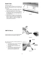
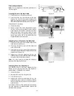
Page 10: ...o the table top in several places to ensure it is parallel with the table top Adjust as needed and tighten all screws Adjust as needed and tighten all screws with a 10mm wrench XACTA Fence Screw the lock lever knob into the threaded handle on the XACTA Fence II as shown in Figure 12 The lock lever has three functional positions as shown in Figure 13 The upright position permits mounting and remova...

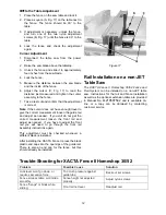
Page 11: ... of the right miter slot and lock it 2 The fence should be even with the miter slot from front to back 3 If the fence is not even along the length of the miter slot unlock the fence remove it and turn upside down Figure 16 4 Adjust one of the two setscrews E Fig 16 until the fence is even with the miter slot edge along its entire length when locked Note You may need to re adjust the clamping press...

Page 12: ... get the correct measurement loosen the front rail and adjust as needed If you have to adjust the front rail you will need to go through the front rail assembly instructions again This adjustment must be checked whenever a different blade is installed After installing the XACTA Fence II press the black plastic end caps into the openings of the guide rail There is also an end cap for the fence but ...

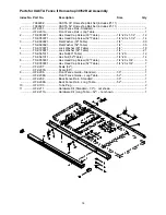
Page 13: ...t Side Plate 1 5 TS 0640071 Lock Nut 1 4 20 10 6 TS 0271031 Socket Set Screw 3 8 16 x 3 8 2 7 3575081 Fluoroway Pad 2 8 XF2 108 Pad Set 1 9 XF2 9 Carriage Bolt 1 4 20 x 3 4 10 10 TS 081D022 Pan Head Machine Screw 10 32 x 3 8 2 11 TS 0680021 Flat Washer 1 4 2 12 HF2 112 Cursor 1 13 HF2 113 XACTA Fence Label 1 14 XF2 129 JET Label 1 15 TS 0640071 Lock Nut 1 4 20 1 16 TS 0640081 Lock Nut 5 16 18 1 17...

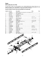
Page 14: ... 0680021 Flat Washer 52 Table 1 4 35 4 TS 0720071 Lock Washer 30 Table 1 4 18 TS 0720071 Lock Washer 52 Table 1 4 21 5 TS 0561011 Hex Nut 30 Table 1 4 20 12 TS 0561011 Hex Nut 52 Table 1 4 20 14 6 TS 0050031 Hex Head Cap Screw 30 Table 1 4 20 x 3 4 6 TS 0050031 Hex Head Cap Screw 52 Table 1 4 20 x 3 4 7 7 XF2 207 Scale 52 1 XF2 207A Scale 30 1 8 HF2 208 Front Fence Guide Standard 30 1 HF2 208A Fro...

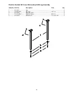
Page 15: ...A Fence II Homeshop 30 52 Leg Assembly Index No Part No Description Size Qty 1 XF2 301 Leg 2 2 TS 0561031 Hex Nut 3 8 16 2 3 XF2 303 Adjusting Foot 2 4 TS 1533052 Machine Screw M5 16 8 5 XF2 305 Metal Insert 30 x 30 x 3 8 2 ...

Page 16: ...16 427 New Sanford Road LaVergne Tennessee 37086 Phone 800 274 6848 www jettools com ...

Reviews: