12
9.2
Operating controls
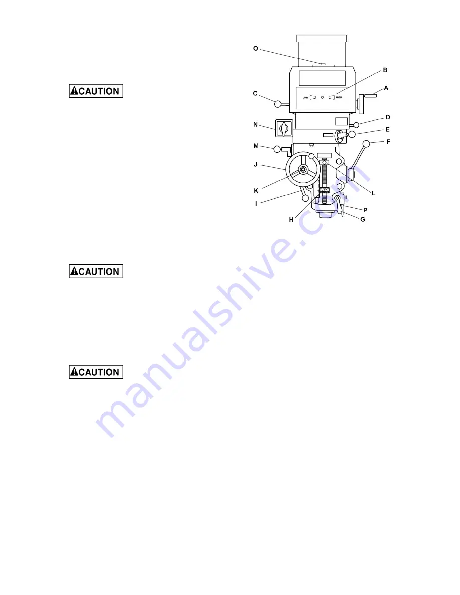
Refer to Figure 9-1.
A.
Variable speed control
(A, Figure 9-1) –
Turn handwheel to adjust spindle speed.
Change spindle speed
only when motor is running. Failure to
comply may result in damage to drive
mechanism.
B.
Variable speed dial indicator
(B) –
Indicates selected speed in high or low
range.
C.
Spindle brake
(C) – Move in either direction
to stop spindle
after power has been turned
off.
D.
Speed range lever
(D) – Push handle
inward and move to desired position. Upper
position is high speed. Middle position is
neutral. Low position is low speed (back
gear engagement). A label is affixed near
the lever for reference.
Do not move Speed Range
Lever (D) while motor is running. Turn off
machine and rotate spindle by hand to
facilitate changing lever positions.
E.
Auto feed engagement lever
(E) – To
engage auto feed, stop spindle, then pull
knob outward and move lever to opposite
hole. Engage pin in hole. A label is affixed
near the lever for reference.
Auto feed may be
engaged when spindle is rotating,
however, it must be engaged gently to
avoid damage to worm gear.
Do not use auto feed at spindle
speeds above 3000 R.P.M.
It is recommended that auto feed
lever be disengaged when not in use.
This avoids unnecessary wear on
worm gear.
Maximum auto feed loading is a 3/8"
(9.5mm) diameter bit for drilling in
steel. Use manual feed for bits larger
than 3/8".
F.
Coarse feed handle
(F) – Used for non-
precision drilling operations and for moving
quill to a specific depth. Rotate counter-
clockwise to lower spindle. A return spring
will retract spindle automatically once
handle is released.
Figure 9-1: Controls
G.
Quill lock
(G) – Rotate handle clockwise to
lock quill in desired position; counter-
clockwise to release.
H.
Micrometer adjusting nut
(H) – Used for
setting spindle depth, according to adjoining
scale. Press button to rapidly slide nut for
general positioning. Release button and
rotate nut for fine adjustment.
Note:
One
complete rotation of micrometer adjusting
nut equals 0.025” (0.635mm) of spindle
travel.
I.
Feed trip control lever
(
I
) – Engages
overload clutch on pinion shaft when lever is
positioned to the left. Stays engaged until
quill stop comes into contact with
micrometer adjusting nut (forcing feed
control lever to drop out automatically), or
until lever is released manually by moving
lever to the right.
J.
Manual fine feed handwheel
(J) – Feed
direction control knob (K) must be in neutral
position. The feed control lever (
I
) must be
engaged.
Note
: Manual feed handwheel
may be removed when not in use.
K.
Feed direction control
(K) – located in
center of manual feed handwheel. Position
of knob depends upon direction of spindle
rotation. If boring with right hand cutting
tools, pull feed knob towards operator until
clutch becomes engaged. Neutral position is
between forward and reverse position.
Summary of Contents for 691050
Page 7: ...7 5 0 JTM 1050VS2 Machine dimensions Figure 5 1 machine dimensions ...
Page 21: ...21 13 1 1 JTM 1050VS2 Upper Head Assembly Exploded View ...
Page 25: ...25 13 2 1 JTM 1050VS2 Lower Head Assembly Exploded View ...
Page 29: ...29 13 3 1 JTM 1050VS2 Column and Base Assembly Exploded View ...
Page 36: ...36 14 0 Electrical connections for JTM 1050VS2 ...
Page 38: ...38 This page intentionally left blank ...
Page 39: ...39 This page intentionally left blank ...
Page 40: ...40 427 New Sanford Road LaVergne Tennessee 37086 Phone 800 274 6848 www jettools com ...


