


14
3. Make sure bolts on left/floating vise (M
2
) are
loosened. Use handwheel to push vise against
workpiece until it conforms to workpiece angle.
Tighten bolts.
4. To expand clamping capacity, remove fixed jaw
from inner holes and install it in outer holes.
7.9
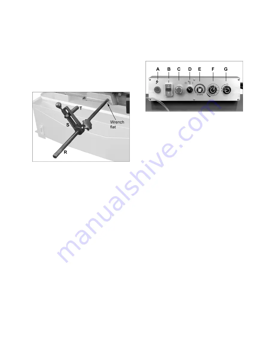
Work stop adjustment
The work stop assembly (Figure 7-7) allows multiple
pieces to be cut to identical length.
Screw rod (R) into hole in base, move bracket (S),
and stop (T) to desired positions, and tighten all
handles/levers.
Figure 7-7: work stop
7.10
Limit switch adjustment
The limit switch has been set so that the motor shuts
off immediately after blade has cut through the
material and just before the head comes to rest.
Adjustment is needed if blade continues to run
after
completion of cut, or blade shuts off
before
completion of cut. Loosen jam nut and turn stop
screw (V, Figure 7-6) as required. Retighten jam nut.
8.0
Operating controls
Refer to Figure 8-1.
Power indicator light (A)
– Illuminates when
machine is receiving electrical power.
Blade start/stop (B)
– Controls motor/blade
operation.
Emergency stop (C)
– Press to instantly stop all
electrical functions (bow will continue its descent).
To restart machine, rotate E-stop button clockwise
until it releases. NOTE: The E-stop is designed for
quick emergency shut-down. For normal blade
stopping, use the
off
button.
Coolant switch (D)
– Turn knob to “I” to start
coolant flow. Turn to “O” to stop coolant flow. Flow
can be regulated by the two valves behind the slide.
Blade speed (E)
– Turn clockwise to increase
speed.
Feed rate control (F)
– Sets speed of bow descent,
i.e. amount of downward force that is applied to
workpiece. The feed rate is proportional to the
opening of the valve; turn knob counterclockwise to
increase feed rate; clockwise to reduce feed rate.
Feed on/off selector (G)
– Turn knob to “I” to open
hydraulic cylinder and allow bow descent; turn to “O”
to hold bow in raised position.
Figure 8-1
9.0
Prior to Operation
Inspect the following before operating the band saw.
1. Check that blade tooth direction matches arrow
on blade guides.
2. Check to see that blade is properly seated on
wheels with correct tension (approximately
25,000 lbs.).
3. Set blade guide brackets as close to work as
possible without obstruction.
4. Check for slight clearance between rear support
bearing and back of blade.
5. Select proper speed and feed rate for material
being cut.
6. Material must be securely clamped in vise.
7. Check to see that cutting fluid/coolant level is
adequate and turn on coolant pump if material
requires it. Machine should be filled with proper
amount of coolant mixture. Follow directions on
coolant manufacturer’s label and fill coolant
tank by pouring through the chip tray.
8. Do not start cut on a sharp edge.
9. Keep machine lubricated. See
sect. 11.1
.
Summary of Contents for 424469
Page 20: ...20 14 1 1 HBS 916EVS 1018EVS Bed and Base Assembly Exploded View...
Page 21: ...21 14 1 2 HBS 916EVS Bow Assembly Exploded View...
Page 22: ...22 14 1 3 HBS 1018EVS Bow Assembly Exploded View...
Page 29: ...29 14 2 1 HBS 916EVS 1018EVS Gear Speed Reducing Box Exploded View...
Page 31: ...31 15 0 Electrical Connections HBS 916EVS 1018EVS...


