


17
When finished:
5. Press and hold the SET button until indicator
“SET” flashes,
6.
Press
SET again (no longer than 1 second).
The indicator “SET” disappears and the
value you just input is displayed on the LCD.
From this point on, any table movement will be
based off this setting. The setting will be kept in
the device’s memory, even when the digital
display is turned off and only needs resetting
after a battery has lost charge and needs
replacing.
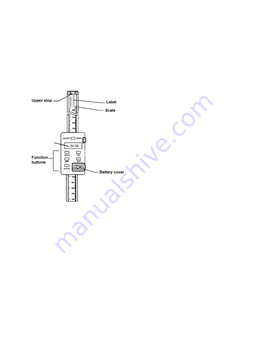
LCD
Figure 19
Setting the DRO – Relative Measurement
Periodically during sanding operations, it may be
desirable to display the amount of material to be
removed from a previously sanded board.
With the sander at the last thickness setting for
that board:
1. Press ABS until "INC" appears. This toggles
the DRO from
Absolute
to
Relative
mode.
2. Press the ON/OFF button for less than three
seconds. The digital display resets to zero.
Raising the table will represent the
additional material to be sanded from a
board from the previous setting.
3. To toggle back to
Absolute
mode, press
ABS again.
IMPORTANT:
Always place the digital display in
relative
(“INC”) mode before turning it off. If you
turn it off while in
absolut
e (“ABS”) mode, your
absolute setting will default to
zero
.
MM/INCH
Pressing this button toggles back and forth
between
standard
(inches) and
metric
(mm), and
can be done at any time without affecting saved
settings.
HOLD
The
Hold
button is used to record a critical
setting for reference for the purpose of later
resetting to that same setting.
For example: In the event that sanding a board
is aborted in the middle of the operation:
1. Press the HOLD button. The dimension is
"frozen" in the display.
2. Lower the table to remove the board.
3. Make a mental note of the "frozen"
dimension (from Step 1).
4. Press HOLD again to return to normal
measurements.
5. Adjust the table back to its original (frozen
display) position.
TOL
This function is not generally used in sanding
operations, but is here explained for reference.
Press TOL, and an up-arrow indicator will
appear, as well as a flashing “SET” indicator.
You can now change the upper tolerance limit.
Hold down the TOL button and each digit
flashes in turn. When the digit you want flashes,
release the TOL button.
Press TOL button once (no longer than 1
second) and that digit will increase each time
TOL is pressed.
When finished, press and hold TOL button until
indicator “SET” flashes. While indicator “SET” is
flashing, press SET button to change the arrow
to the down-arrow indicator. You can now
change the lower tolerance limit in the same
manner as you changed the upper tolerance
limit.
When finished setting the lower tolerance limit,
while indicator “SET” is flashing, press SET
button (no longer than 1 second). The device is
now in tolerance measuring mode. When the up-
arrow indicator is displayed, it means the
measured value is beyond the upper limit. When
the down-arrow indicator is displayed, the
measured value is below the lower limit. When
the display shows an “OK” indicator, the
measured value is within tolerance.
Summary of Contents for 22-44 Pro-3
Page 35: ...35 Stand Assembly...
Page 37: ...37 Drum Head Assembly...


