background image

6

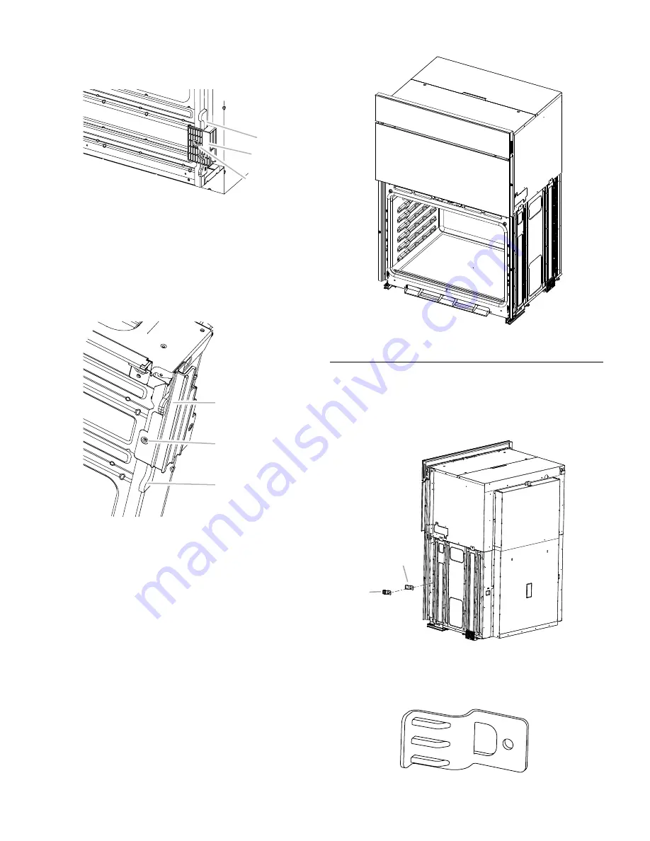
2.

  Install a foot on the left rear spacer using a                            


#8-18 x 

3

8

" screw.


NOTE:

 Position the foot so the long side of the foot 


is facing toward the top of the oven.

A. Spacer

B. Foot

C. #8-18 x 

3

8

" screw

3.

  In the same manner, install a foot on the right rear of             


the oven.

4.

  Install a front foot on the left front spacer using a 


#8-18 x 

3

8

" screw.


NOTE:

 Position the foot so the long side of the foot 


is facing toward the inside of the oven.

A. Front foot

B. #8-18 x 

3

8

" screw

C. Spacer

A

B

C

A

B

C

5.

  In the same manner, install a front foot on the right 


front of the oven.

6.

  Using 2 or more people, place the oven in its upright position.

7.

  Go to the “Make Electrical Connection” section in the


Installation Instructions provided with your built-in oven.

Replace Plastic Spacers

1.

  Remove the screw attaching the plastic spacer (A) to the     


right side of the oven.

2.

  Using the screw removed, install a new plastic spacer (B)


provided with this kit.

A. Plastic spacer

B. New plastic spacer

3.

  In the same manner, remove and replace the plastic spacer  


on the left side of the oven.

B. New plastic spacer

A

B

Summary of Contents for JMW2427DB

Page 1: ...s encastr s micro ondes four 14 D pose de la porte s du four 14 R installation de la porte s du four 14 Positionnement des pieds du four 15 Remplacement des cales d espacement en plastique 16 Installa...

Page 2: ...vide minimum clearance for the oven The recessed installation area must provide complete enclosure around the recessed portion of the oven The oven support surface must be solid level and flush with t...

Page 3: ...location I 45 8 191 4 11 7 48 9 cm bottom of cutout to floor J 253 8 64 4 cm minimum depth of cutout Side View Cleats and spacers must be recessed 13 8 3 5 cm from the front of the cabinet Cabinet Di...

Page 4: ...face where you will place it This surface should be flat and covered with a soft blanket or use the corner posts from your packaging material 2 Open the oven door 3 Locate the oven door hinge locks in...

Page 5: ...tration A in the Remove Oven Door section for the proper locked position 6 Close the oven door 7 When the hinges are properly installed and the door is closed there should be an even gap between the d...

Page 6: ...foot B 8 18 x 3 8 screw C Spacer A B C A B C 5 In the same manner install a front foot on the right front of the oven 6 Using 2 or more people place the oven in its upright position 7 Go to the Make...

Page 7: ...the upper vent piece C away from the lower vent piece D to slide the deflector bracket B between them Some force may be required to flex the upper vent trim C away from the lower vent trim D Some for...

Page 8: ...been on for 5 minutes feel for heat If you do not feel heat or if an error message appears in the display turn off the oven and contact a qualified technician 7 Press CANCEL OVEN Check Operation of Mi...

Page 9: ...les temp ratures maximales permises de 194 F 90 C pour les placards en bois Outillage et pi ces Outils n cessaires Tournevis Phillips M tre ruban Perceuse pour l installation dans un placard mural For...

Page 10: ...eur totale de l ouverture 1 2 x 2 13 mm x 5 1 cm H Emplacement recommand pour le bo tier de connexion I 45 8 191 4 11 7 48 9 cm du fond de l encastrement au plancher J Profondeur minimale de l ouvertu...

Page 11: ...r avec les deux mains 1 Avant de retirer la porte du four pr parer une surface sur laquelle on pourra la poser Cette surface doit tre plate et recouverte d une couverture douce On peut aussi utiliser...

Page 12: ...ce qu elle soit compl tement ouverte Si la porte du four ne s ouvre pas compl tement un angle de 90 degr s r p ter les tapes 1 3 5 Identifier les loquets de charni re de la porte du four dans les angl...

Page 13: ...ale d espacement arri re gauche avec une vis n 8 18 x 3 8 screw REMARQUE Positionner le pied de fa on ce que le c t long du pied soit orient vers le sommet du four A Cale d espacement B Pied C Vis n 8...

Page 14: ...e sur le c t gauche du four B Cale en plastique neuve A B Installation du four 1 l aide d au moins 2 personnes soulever et introduire partiellement le four dans l ouverture d encastrement du placard U...

Page 15: ...let de l vent B avec le ch ssis du four A comme illustr D B A C B D C 4 Avec une vis n 8 18 x 1 4 E pour chaque c t du support de l vent B fixer solidement l vent au four D Support du d flecteur E Vis...

Page 16: ...ise en marche La lampe int rieure du four micro ondes doit s allumer et la dur e de cuisson restante doit s afficher Lorsque l afficheur indique 1 00 minute ouvrir la porte du four micro ondes La cuis...

Reviews: