background image

Installation Instructions Product-Ident: 75181


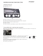
8 Adaptation amplifier - crossover circuit / Insulation of the car doors

8.1

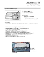
 Carefully remove the moisture protection foil.

8.2


Insulation of the car doors

 - Important tips against vibration-noise (see attached installation recommendation)

8.3

 Adaptation amplifier - crossover circuit: 

Lead 1x speaker cable (1,5 - 4 qmm) from amplifier to the crossover circuit: 

mount of crossover circuit: car door / behind the doorboard

 In order to avoid vibration noise secure all cables with insulating tape e.g.

8.4

 Reinstall the moisture protection foil to fit precisely.

8.5

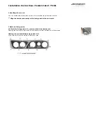
 For the bass performance the speakers are using the volume of the car door:

Place the door card on the car door as template and mark the position for the woofers on the moisture protection foil. Take away the

the door card and cut out 

(u-form see fig.)

 behind the woofers. Stabilize the lateral cutting edges in order to avoid vibration noise

(e.g. use a packing tape)


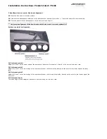
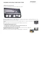
9 Installation of the door card onto the car doors

9.1

 Check up length of the screws and bolts:

in order to prevent damages of mechanic parts of the car doors, please check once again the length of all bolts and

screws on the back side of the door card! No touch with any mechanic parts of the car doors! (Please shorten if

necessary).

9.2

 Put the door card into the upper sealing of the car door. Fit it in contrary order of succession.


 Final inspection after doorboard installation: please check all functions of the operating elements such as seat

adjustment, opening of the glove box, window winder etc.

Summary of Contents for 75181

Page 1: ...t left Audi A3 2 door only part no 75181 1x Hardware bag Audi A3 2 door only part no 75181 71181 8x flat head srew M4 x 30 2x flat head srew M4 x 40 2x flat head srew M4 x 50 22x hex nut M4 4x Velcro strip à 2 5 cm reserve 4x washer 12mm 18x washer 20mm Garantee We grant a manufacturers guarantee of 2 years starting from the date of purchase of the doorboard or sound system from the dealer Within ...

Page 2: ...installation A pillar original mount without mounting device 2 1 Dismount the original speaker grill of the A pillar and the original tweeter Unplug the connecting cables No more need of the original connecting cable and tweeter 2 2 Remove the tweeter out of the mounting holder bayonet catch turn to the right and pull out of the holding device by means of the screw no more need of the mounting dev...

Page 3: ...nts optimal fit Reference points for alignment 3 4 Reference point 1 Adjust the nose on the upper edge of the doorboard above the first woofer directly in the notch of the door card 3 5 Reference point 2 Adjust the nose on the lower edge of the doorboard under the first woofer directly on the notch in the lower edge of the door card 3 6 Reference point 3 Adjust the nose on the lower edge of the do...

Page 4: ... and cut outs Align the doorboard exactly to the fixing points of the door card 5 Mark the fixing points 5 1 Mark the fixing points 1 5_ premounted in the doorboard Pressing the doorboard onto the door card leaves a visible impression of the screws Marking the pre drilled fastening points 6 11 use a thin awl to set the marks on the door card ...

Page 5: ...s for the woofers on the door card Enlarge them approx 1cm approx outer diameter of the woofers 6 3 For a plane alignment of the doorboard also mark the overlapping tray for the cut out IMPORTANT Check all marked cut outs The fastenings of the doorboards must have to be screwed with the door card The fastenings of the door card must not be removed 6 4 Remove the doorboard again and cut out the mar...

Page 6: ...he door card Screw all M4 screws only hand tight Secure all screws with washers and nuts TIP Treat the screw thread with a liquid for screw in type fuse speaker vibrations may loosen the screws after some time 7 2 Check again for precise fit and tighten screws All cutting edges of the doorboards must fit to the door card snugly all around without gap ...

Page 7: ...the door card on the car door as template and mark the position for the woofers on the moisture protection foil Take away the the door card and cut out u form see fig behind the woofers Stabilize the lateral cutting edges in order to avoid vibration noise e g use a packing tape 9 Installation of the door card onto the car doors 9 1 Check up length of the screws and bolts in order to prevent damage...

Page 8: ...g 10 6 Notice You should check the polarity of all woofers after having connected them to the crossover circuit with a 9 volt battery input cable on the side of the amplifier pole of the crossover circuit input to of a 9 Volt battery pole of the crossover circuit input to of a 9 Volt battery All subwoofers must move uniformly Wrong polarity of a subwoofer can totally equalize the bass sound 11 Ins...

Page 9: ...ee fig above or stabilize the backside of the door lining by means of a special material Glass Fibre Filler or stiffening material important keep the cut outs for the door airbags and speakers open affix the backside of the inner door metal with self adhesive asphalt mats see fig by knocking on the car door vibrations caused by mechanic parts e g Bowden pull wire etc and wiring harness may be found o...

Page 10: ...llowing notes serve to help troubleshoot and eliminate faults or malfunctionson your own If the follow ing measures are not effective please call us Info Hotline Tel 0049 7158 95699 0 What can it be if possible cause solution it doesn t sound right wrong polarity on the subwoofers see speaker connection crosover circuit attached wrong see wiring diagram speaker connection door lining and moisture ...

Reviews: