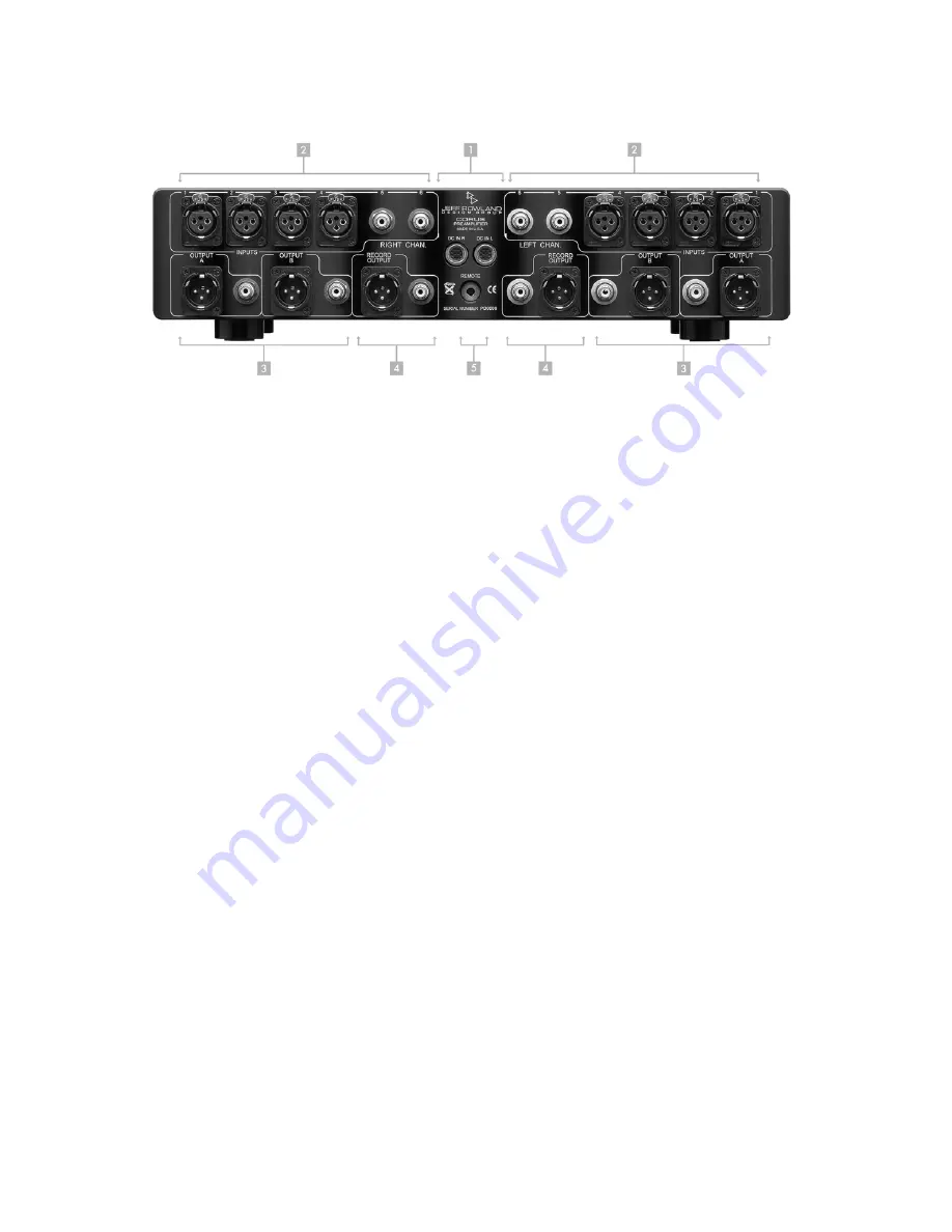
REAR PANEL
Figure 4:
Rear Panel
1.
DC IN R/L POWER INPUT RECEPTACLES.
Two separate DC power cables, one for each
channel, are utilized to connect the power supply to
CORUS
PREAMPLIFIER
.
2.
INPUTS.
Four (4) pair Balanced (XLR), Two (2) pair Unbalanced (RCA) input jacks for each
channel.
3.
MAIN 1/MAIN 2 OUTPUTS.
Two (2) pair Balanced (XLR), Two (2) pair Unbalanced (RCA)
jacks for Main A/Main B outputs for each channel. (
MAIN 1
and
MAIN 2
are mapped to
OUTPUT A
and
OUTPUT B
on the preamplifier back panel)
4.
RECORD OUTPUTS.
One (1) pair Balanced (XLR), One (1) pair Unbalanced (RCA) jacks for
Record Out.
5.
REMOTE SENSOR INPUT CONNECTOR
and
SERIAL NUMBER.
he remote sensor unit
connects to this connector via a 2-meter flexible cable. The wired connection allows full
control of the preamplifier through the infrared handheld remote transmitter. The 2-meter
cable end marked
PREAMP END
must be connected to the preamplifier rear panel. The
preamplifier chassis serial number begins with the letters “PD”.
16


