linear drive type LD100 installation guide version 1.2 page 3 of 3
Test the system:
Before you can test the system, make sure following things are correct:
•
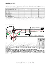
Solid rudder stops should be fitted limiting the rudder travel to an equal travel of 36 degrees from
midships to port and starboard. (PS. In the case of a larger rudder angle than 36°, the tiller centres of
the linear drive should be adjusted accordingly to prevent the linear drive from acting as rudder stop)
•
Make sure all bolted parts (tiller pins, rosejoints, mounting plate bolts, tillerarm, etc) are firmly tightened
and will not come loose even when exposed to heavy vibrations. Use loctite when necessary.
•
No part of the drive unit should contact the vessel, the quadrant, or the tiller arm throughout the full
range of movement.
•
The drive unit should be mounted with the motor pointing sideways if possible. Mounting the drive unit
with the motor pointing up or down may generate more friction, and therefore cause more wear over
time.
•
Make sure no (drip) water can reach the drive unit as it is NOT waterproof. When the drive is
submerged or heavily splashed with water, immediately remove the drive unit, dry it and return it to our
factory for overhaul. Continuing using the wet drive will jeopardise the functioning and it will be not
repairable anymore. The IP rating code of the LD100 drive unit is 43. Please read more at this web link:
http://en.wikipedia.org/wiki/IP_Code
Connect the electronics. Make sure
the autopilot is set to “reversible drive” or equivalent. Don’t use settings like
“solenoid” or “hydraulic drive” as these settings will disable the speed control of the autopilot leaving the drive
running at 100% speed or 0%, but nothing in between. Make sure the clutch voltage is set to 12 volts. Some
autopilots pulse the clutch and slowly drop to 6 Volts instead of a steady 12 volts. A contactor (relais) with a
capacitor should be used. See the separate manual on our FTP server
for info on your specific autopilot electronics.
When the drive doesn’t react to the electronics, test the drive by bypassing the electronics: Connect a plus and
minus wire to the battery or fuse box and first connect the clutch, one should hear a click when connecting and
disconnecting. With the clutch under power, connect power for a short time to the motor cables. The system
should get in motion now. Don’t connect the cables too long as the drive will try to continue, even when the
rudder stops are reached, with potential damage to the structure and drive unit. If motion is detected, one can
rule out the drive causing the malfunction.
Maintenance:
The linier
drive is “greased for life”, so should not be opened. No maintenance is required except for periodic
checks of all bolted connections. As the rudder system, the steering system and the autopilot drive is exposed
to heavy vibrations (mainly when cruising by motor), all bolted connections should be yearly checked. The only
parts that could wear in time are the balls of the drive. These balls are easy exchangeable and available for
around 10 € each from any Jefa distributor.
Declaration of conformity:
I, Stig Jensen of Jefa Marine Steering ApS, Nimbusvej 2, 2670 Greve, Denmark, confirm that the Jefa linier
drive, when fitted in accordance with these installation instructions, will meet the requirements of the Electro
Magnetic Compatibility Directive Standard contained within Standard No. 60945/A1.
Signed:…………………………………………………………….
Date: 08-05-2008
Stig Jensen


