background image

Chapter 

2  Part C  lnline six-cylinder engine 

Oil  pump  mounting  bolt 

Short 

1 0  

Long 

17 

Rear  main bearing  cap bolts 

8 0  

Rocker arm bolts 

1 9  

Rocker  arm cover-to-cylinder  head bolts 

With RTV 

28 in-lbs 

With permanent gasket 

55 

in-lbs 

Tensioner  bracket-to-block  bolts 

14 

Timing  chain cover-to-block 

Bolts 

Studs 

1 6  

Vibration  damper  center  bolt  (lubricated) 

80 

1  General information 

This Part of Chapter 

is devoted t o  in-vehicle repair procedures for 

the 

six-cylinder engine. All information concerning engine removal 

and installation  and  engine block and cylinder head overhaul can be 
found in Part 

D of  this  Chapter. 

The following repair procedures are based on the assumption that 

the engine is installed in the vehicle.  If the engine has been removed 
from the vehicle and mounted on a stand,  many of the steps outlined 
in  this Part  of  Chapter  2  will not apply. 

The Specifications included in this Part of Chapter  2 apply  only t o  

the procedures contained in this Part. Part 

D of Chapter 2 contains the 

Specifications necessary for cylinder head and engine block rebuilding. 

Repair operations  possible  w i t h  the engine in the vehicle 

Many major repair operations can be accomplished without removing 

the  engine  from the  vehicle. 

Clean the engine compartment and the exterior of the engine with 

some type of pressure  washer  before any work is done. It  will make 
the job easier and help keep dirt out of the internal areas of the engine. 

Remove the hood,  if necessary,  to improve access t o  the engine as 

repairs  are  performed  (refer t o  Chapter  11  if  necessary). 

If  vacuum,  exhaust, oil or  coolant leaks develop,  indicating  a need 

for gasket or seal replacement, the repairs can generally be made with 

the engine in the  vehicle.  The intake  and exhaust manifold  gaskets, 
timing cover gasket,  oil pan gasket,  crankshaft  oil seals and cylinder 
head gaskets  are  all  accessible  with the engine  in place. 

Exterior  engine  components,  such  as  the  intake  and  exhaust 

manifolds, the oil pan (and the oil pump), the water pump,  the starter 
motor, the alternator,  the distributor and the fuel system components 
can be  removed  for repair  with the  engine in place. 

Since the cylinder heads can be removed without pulling the engine, 

valve component servicing can also be accomplished with the engine 

in  the  vehicle.  Replacement  of  the  camshaft  and  timing  chain  and 

sprockets  is also possible  with the engine  in the vehicle. 

In extreme cases caused by a lack  of necessary equipment,  repair 

or replacement of piston rings, pistons,  connecting rods and rod bear- 
ings is possible  with the engine in the vehicle. However, this practice 
is not recommended because of the cleaning and preparation work that 
must be  done  t o  the components  involved. 

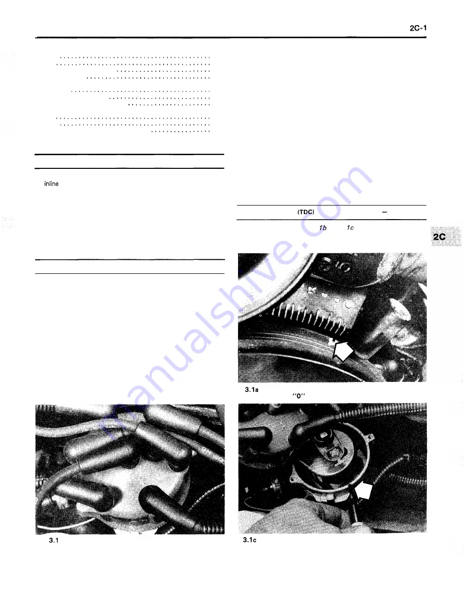
3  Top  Dead Center 

for number  one piston 

locating 

Refer  to  illustrations 

3. 

la, 

3. 

and 

3. 

See Chapter 2,  Part A,  Section 

for this procedure,  but refer to the 

illustrations and  specifications  included  in this Section. 

Align the notch (arrow) on the vibration damper  w i t h  

the 

on the timing  chain cover 

b  Locate  the number  one spark plug terminal on the 

distributor  cap,  make a mark  on the distributor  housing, 

directly under  the number one plug terminal, 

. . .  

. . .  

then remove the distributor  cap and verify that the 

rotor is pointing at the mark  (arrow) 

The Motor Manual Guy

Summary of Contents for cherokee 1989

Page 1: ...2 Tune up and routine maintenance 1 1 Chapter 2 Part A Four cylinder engine 24 1 Chapter 2 Part B V6 engine 28 0 Chapter 2 Part C Inlinesix cylinderengine 2C 0 Chapter 2 Part D General engine overhaul...

Page 2: ...The Motor Manual Guy...

Page 3: ...The Motor Manual Guy...

Page 4: ...Certification label is affixed to the left front door pillar This plate is located on the radiator support on the driver s side It contains information on the vehiclemodel emissioncertification engin...

Page 5: ...21 363 The three speed automatic transmission numbers are stamped on the edge of the left side of the case Typical transfer case ID tag BA 1015 manual transmission ID number location TRANSMISSION n Th...

Page 6: ...rs are stamped on the left edge of the case see illustration The ID plate on four speed automatic transmissions is located on the right rear of the case see illustration Transfer case identification n...

Page 7: ...andard bolt Also most standard bolts have slashes radiating out from the center of the head to denote the grade or strength of the bolt which is an indication of the amount of torque that can be appli...

Page 8: ...r bolt Overtightening the fastener can weaken it and cause it to break while undertightening can cause it to eventually come loose Bolts screws and studs dependingon the material they are made of and...

Page 9: ...hammer can be used if a block of wood is placed between the hammer and the part Do not hammer on cast parts or parts that could be easily damaged With any particularly stubborn part always recheck to...

Page 10: ...ump Timing light Compression gauge with spark plug hole adapter Hydraulic lifter removal tool Ridge reamer Damperlsteering wheel puller General purpose puller Valve spring compressor Valve spring comp...

Page 11: ...un 43U 0 1 Uo SUajx3 2ay31ej a q sjan au sl2a s jay3o s Aljadojd sap yan jsow 6u unj lo Ajessa3au Alajnlosqe aje Aayj asnemq aJay pauo luaw s I slooj le ads 40 JSII aayl u papnpu a x Aay y 6 n o y l...

Page 12: ...tools that will actually be used Tool stores will often be the only source of some of the special tools that are needed but regardless of where tools are bought try to avoid cheap ones especially whe...

Page 13: ...ions in the running at idle speed disconnect the jumper cables in the reverse order numerical order shown note that the negative cable of the of connection booster battery is NOT attached to the negat...

Page 14: ...be attached to the main structural members of the vehicle not the bumper or brackets Tow hooks are attached to the frame at both ends of the vehicle However they are for emergency use only and should...

Page 15: ...oly penetrants loosen and lubricate frozen rusted and corroded fasteners and prevent future rusting or freezing Heat sink grease is a special electrically non conductive grease that is used for mounti...

Page 16: ...that they do contain asbestos Fire Remember at all times that gasoline is highly flammable Never smoke or have any kind of open flame around when working on a vehicle But the risk does not end there A...

Page 17: ...g cm2 X 0 068 Atmospheres atm X 0 069 Bars X 6 895 Kilopascals kPa X 0 01 Kilograms force per square centimetre kgf cm2 kg cm2 X 1 152 Kilograms force centimetre kgf cm kg cm X 0 113 Newton metres Nm...

Page 18: ...haft Knock or clunk when transmission is under initial load just after transmission is put into gear 53 Leaks at front of driveshaft 52 Metallic grating sound consistent with vehicle speed 54 Scraping...

Page 19: ...then adjust the ignition timing as soon as possible Chapter 1 16 Broken loose or disconnected wires at the ignition coil or faulty coil Chapter 5 17 Timing chain failure or wear affecting valve timin...

Page 20: ...eed out of adjustment Chapter 1 15 Hesitation or stumble during acceleration 1 lgnition timing incorrect Chapter 1 2 lgnition system not operating properly Chapter 5 3 Dirty or clogged carburetor or f...

Page 21: ...ore rapid as the engine accelerates indicates worn or damaged connecting rod bear ings Chapter 2 The procedure for locating the problem cylinder is the same as described in Paragraph 1 3 An overlappin...

Page 22: ...tigued Remove clutch cover pressure plate assembly and inspect 4 Leakage of fluid from clutch hydraulic system lnspect master cylinder operating cylinder and connecting lines 5 Air in clutch hydraulic...

Page 23: ...irst remove all built up dirt and grime from the transmission Degreasing agents and or steam cleaning will achieve this With the underside clean drive the vehicle at low speeds so the air flow will no...

Page 24: ...tires and check tire pressures Chapter 1 3 Front wheel bearings loose worn or damaged Chapter 1 4 Insufficient differential oil Chapter 1 5 Defective differential 59 Knocking sound when starting or s...

Page 25: ...ake application 1 Wheel bearings damaged worn or out of adjustment Chapter 1 2 Caliper not sliding properly due to improper installation or obstruc tions Remove and inspect 3 Rotor not within specific...

Page 26: ...m 5 Defective power steering pump 83 Steering wheel fails to return to straight ahead position 1 lncorrect front end alignment 2 Tire pressures low 3 Steering gears improperly engaged 4 Steering colum...

Page 27: ...hrottlelinkage inspection Tire and tire pressurechecks Tire rotation Transfer case lubricant change 4WD models Transfercase lubricant level check f4WD models Tune up general information Underhood hose...

Page 28: ...hers Inlinesix cylinderengine 12 degrees BTDC 19 degrees BTDC V6 ENGINE 12 degrees BTDC ENGINE FRONT c3 10 degrees BTDC 8 degrees BTDC Not adjustable General Engine idle speed carbureted modelsonly Fo...

Page 29: ...eld wiper blades Section 11 Every 7580 miles or 12 months whichever comes first All items listed above plus Change the engine oil and filter Section 12 Lubricate the chassis components Section 13 lnsp...

Page 30: ...em hose and fitting 8 CCV fresh air hose 2 Clutch fluid reservoir 9 Engine oil filler cap 3 Brake fluid reservoir 10 Engine oil dipstick 4 Windshield washer reservoir 1 1 Radiator hose 5 Air cleaner h...

Page 31: ...e shown 7 Front driveshaft slip joint grease fitting 2 Transmission 3 Engine oil drain plug 4 Exhaust pipe 5 Brake hose 6 Steering linkage 7 Steering damper 8 Front driveaxle 9 Front disc brake calipe...

Page 32: ...The Motor Manual Guy...

Page 33: ...ompression check indicates serious in ternal engine wear a conventional tune up will not improve the per formance of the engine and would be a waste of time and money Because of its importance the com...

Page 34: ...running The cap should only be removed when the engine is off and cold 9 The coolant level in the reservoir should be checked regularly Warning Do not removethe radiatorcap orpressurebottle cap to ch...

Page 35: ...o these batteries at any time If a maintenance type battery is installed the caps on the top of the battery should be removed periodically to check for a low water level This check is most critical du...

Page 36: ...ection of the tires may spare you the inconvenience of being stranded with a flat tire It can also provide you with vital in formation regarding possible problems in the steering and suspension system...

Page 37: ...eel or hubcap and push the gauge firmly onto the valve stem see illustration Note the reading on the gauge and compare the figure to the recommended tire pressure shown on the placard on the driver s...

Page 38: ...eck and maintenance Refer to illustrations 8 1 8 8a 8 8b 8 8 and 8 8d Warning Certain precautions must be followed when checking and servicing the battery Hydrogen gas which is highly flammable is alw...

Page 39: ...f petroleum jelly or grease to the terminals and cable clamps after they are assembled 9 Make sure that the battery carrier is in good condition and that the hold down clamp bolt is tight If the batte...

Page 40: ...his for a minimal charge 10 Underhood hose check and replacement General 1 Caution Replacement o f air conditioning hoses must be left to a dealer service department or air conditioning shop that has...

Page 41: ...anges are the most important preventive mainte nance procedures that can be done by the home mechanic As engine oil ages it becomesdiluted and contaminated which leads to premature engine wear 2 Altho...

Page 42: ...plug with a clean rag Small metal particles may cling to the plug and would immediately contaminate the new oil 12 Clean the area around the drain plug opening and reinstall the plug Tighten the plug...

Page 43: ...buy grease fittings which will thread into the component A dealer or auto parts store will be able to supply the correct fittings Straight as well as angled fittings are available 3 For easier access...

Page 44: ...nd retard wear 1 4 Suspension and steering check Refer to illustration 14 4 1 Indications of a fault in these systems are excessive play in the steering wheel before the front wheels react excessive s...

Page 45: ...squeeze bottle 4 Install and tighten the plug and check for leaks after the first few miles of driving 17 Differential lubricant level check Refer to illustration 17 2 Note 4WD vehicles have two diff...

Page 46: ...d 4 These vehicles are equipped with a wear sensor attached to the inner pad This is a small bent piece of metal which is visible from the inner side of the brake caliper When the pad wears to the spe...

Page 47: ...ttached to the fuel tank Look for loose connections deteriorated hoses crimped lines and other damage Follow the lines to the front of the vehicle care fully inspecting them all the way Repair or repl...

Page 48: ...periodically to prevent major engine dam age 2 The number of belts used on a particular vehicle depends on the accessories installed Drivebelts are used to turn the alternator power steering pump wat...

Page 49: ...ng moved or the part being pried against 9 To replace a belt follow the above procedures for drivebelt adjust ment but slip the belt off the pulleys and removeit Since belts tend to wear out more or l...

Page 50: ...ritical to the SOLE VAC VACUUM ACTUATOR 30 7 Before checking the idle speed on four cylinder engines disconnect the vacuum hose from the sole vac vacuum actuator performance of the engine itself as we...

Page 51: ...w one to make sure they re the same length and design 10 Reinstall the spring in the carburetor body 1 1 Place the filter in position a gasket is usually supplied with the new filter and tighten the n...

Page 52: ...ir filter as previously described then locate the PCV filter on the inside of the housing COVER ELEMENT 32 2a On carburetor equipped models remove the air cleaner wing nut disconnect the clips lift th...

Page 53: ...ignition timing marks are located at the front of the engine four cylinder shown pick up lead Instead use an adapter between the spark plug andplug wire If the insulation on the plug wire is damaged t...

Page 54: ...ags newspapers and wrenches under the trans drain out mission 3 Remove the transmission drain plug at the bottom of the case see illustration 16 1 and allow the oil to drain into the pan 4 After the o...

Page 55: ...and allow the old lubricant to drain completely 5 Carefully clean and install the drain plug after the case is completely drained Tighten the plug to the specified torque 6 Fill the case with the spec...

Page 56: ...ilities to remove the old races and press new ones in Note that the bearings and races come as matched sets and old bearings should never be installed on new races 15 Use high temperature front wheel...

Page 57: ...Refer to illustrations 39 4a 39 4b 3 9 4 and 39 5 Warning Antifreeze is a corrosive and poisonoussolution so be careful not to spill any of the coolant mixture on the vehicle s paint or your skin If t...

Page 58: ...cleaning and replacement Refer to illustration 40 11 Check 1 The PCV valve or CCV hose is located in the rocker arm cover 2 With the engine idling at normal operating temperature pull the valve with h...

Page 59: ...new spark plugs be sure to obtain the correct plug type for your particular engine This information can be found on the Vehicle Emission Controllnformation label located in the engine compartment on t...

Page 60: ...ase Once the wire is clean check for holes burned areas cracks and other damage Don t bend the wire exces sively or the conductor inside might break 6 Disconnect the wire from the distributor cap A re...

Page 61: ...ndi tions Recommendation When new spark plugs are installed re place with plugs of the same heat range ASH DEPOSITS Symptoms Light brown de posits encrusted on the side or center electrodes or both De...

Page 62: ...end of the sensor C DO not usecleaningsolventsof any kind on theoxygen sensor d Do not drop or roughly handle the sensor 1 The sensor is located in the exhaust manifold or exhaust pipe and is accessib...

Page 63: ...2 Rocker arm cover removal and installation 4 Rocker arms and pushrods removal inspection and installation 5 Spark plug replacement See Chapter 1 Timing chain and sprockets removal inspection and ins...

Page 64: ...of the engine Depending on the components involved remove the engine cover and if necessary the hood to improve access to the engine as repairs are performed refer to Chapter 11 if necessary If vacuu...

Page 65: ...nkshaft pulley is aligned with the 0 on the timing plate located at the front of the engine see illustration 9 Look at the distributor rotor it should be pointing directly at the mark you made on the...

Page 66: ...ocker arm covers RTV or a gasket may be used On models equipped with an aluminum rocker arm cover RTV must be used Later models use a pre cured reuseable gasket install these without sealant 9 Place t...

Page 67: ...ls begin with cylinder number one and work on the valves for one cylinder at a time Move from cylinder to cylinder following the firing order sequence see the Specifications 4 Thread an adapter into t...

Page 68: ...all the valve spring retainer Compress the valve spring and carefully position the keepers in the groove Apply a small dab of grease to the inside of each keeper to hold it in place see illustration 1...

Page 69: ...exhaust leaks SPACER NUT 8 5 Exhaust manifold mounting details Refer to illustrations 9 9 and 9 15 Warning Allow the engine to cool to room temperaturebefore following this procedure 1 Remove the rock...

Page 70: ...fective it ll be evident from the shock felt at the retainer as the valve opens 2 The most likely cause of a noisy valve lifter is a piece of dirt trapped between the plunger and the lifter body 3 Rem...

Page 71: ...ace it securely on jackstands 4 If the vehicle is equipped with a manual transmission apply the parking brake and put the transmission in gear to prevent the crankshaft from turning then remove the cr...

Page 72: ...cable from the battery then remove the vibration damper see Section 11 2 Note how the seal is installed the new one must face the same direction Carefully pry the oil seal out of the cover with a sea...

Page 73: ...lean the cover and all sealing surfaces removing any traces of gasket material Drive the old oil seal out from the rear of the timing chain cover and replace it with a new one see Section 12 Also repl...

Page 74: ...ive chain slack and teeth that are deformed chipped pitted or discolored call for replacement Always replace the sprockets and chain as a set Inspect the tensioner for excessive wear and replace it if...

Page 75: ...occurred and a new camshaft should be installed Removal Refer to illustration 15 19 9 Set the number one piston at Top Dead Center see Section 3 10 Disconnect the negative cable from the battery 11 Re...

Page 76: ...d coolant and change the oil and filter see Chapter 1 32 Start the engine and check the ignition timing Check for leaks and unusual noises 16 Oil pan removal and installation Refer to illustration 16...

Page 77: ...driveplate from the crankshaft Since the fly wheel is fairly heavy be sure to support it while removing the last bolt 6 Clean the flywheel to remove grease and oil lnspect the surface for cracks rivet...

Page 78: ...driveplate see Section 18 5 Using a seal removal tool or a large screwdriver carefully pry the seal out of the block seeillustration Don t scratch or nick the crank shaft in the process 6 Clean the bo...

Page 79: ...see if the rubber is cracked hardened or separated from the metal plates Sometimes the rubber will split right down the center 5 Check for relative movement between the mount plates and the engine or...

Page 80: ...formation See Chapter 2D Top Dead Center TDC for number one piston locating 3 Engine removal and installation See Chapter 2D Valve lash adjustment 6 Exhaust manifolds removal and installation 9 Valve...

Page 81: ...lop indicating a need for gasket or seal replacement the repairs can generally be made with the engine in the vehicle The intake and exhaust manifold gaskets timing cover gasket oil pan gasket cranksh...

Page 82: ...rm stud nuts Store them separately in marked containers to ensure that they will be reinstalled in their original locations Note I f the pushrodsare the only itemsbeingremoved loosen each nutjust enou...

Page 83: ...three cylinder exhaustvalves with the crankshaft in this position using the method just described 7 Rotate the crankshaft until the number four piston is at TDC on the compression stroke and adjust th...

Page 84: ...roove to hold RTV sealant when the manifold is installed on the engine 19 Thoroughly clean the intake manifold removing all chips and tape 20 Apply a 3116 inch bead of RTV to each of the ridges betwee...

Page 85: ...ining manifold bolts and separate the manifold and heat shield from the engine 19 Installation is the reverse of the removal procedure Be sure to thoroughly clean the cylinder head and manifold surfac...

Page 86: ...sert a bar into one of the exhaust ports then carefully lift on the tool 33 To install the head refer to Steps 15 through 21 11 Vibration damper removal and installation Refer to illustrations 11 5 an...

Page 87: ...cover 9 Using a block of wood and hammer drive the new seal into the cover until it is completely seated see illustration 10 Install the timing chain cover by reversing the removal procedure in Secti...

Page 88: ...orn timing chain and sprockets may result in erratic engine perform ance loss of power and lowered gas mileage 6 If any one component timing chain or either sprocket requires replacement the other two...

Page 89: ...n be removed with a small magnet or even with your fingers A machinist s scribe with a bent end can be used to pull the lifters out by positioning the point under the retainer ring in the top of each...

Page 90: ...all the remaining components in the reverse order of removal by referring to the appropriate Chapter or Section 17 Adjust the valve lash refer to Section 6 18 Have the air conditioning system if equip...

Page 91: ...he specified torque 5 Reinstall the oil pan 19 Flywheel driveplate removal and installation Refer to Chapter 2 Part A Section 20 for this procedure Be sure to use the torque specifications in this Par...

Page 92: ...984 models with two piece neoprene seals Refer to illustrations 20 17 20 20 and 20 21 13 Always service both halves of the rear main oil seal While replace ment of this seal is much easier with the en...

Page 93: ...Note Special tools as noted in the Steps which follow are required for this procedure They are available from your dealer or may in some cases be rented from an auto parts store or tool rental shop 28...

Page 94: ...stallation 1 2 Exhaust manifold removal and installation 8 Top Dead Center TDC for number one piston locating 3 Flywheelldriveplate removal and installation 17 Valve spring retainer and seals replacem...

Page 95: ...11 if necessary If vacuum exhaust oil or coolant leaks develop indicating a need for gasket or seal replacement the repairs can generally be made with the engine in the vehicle The intake and exhaust...

Page 96: ...y with a soft face mallet see illus tration Do not pry on the gasket flange Note These covers have a reusable pre cured RTV gasket that is attached to the cover 5 Clean the sealing surfaces removing a...

Page 97: ...rfaces before engine oil pressure builds up Install the rocker arms fulcrums bridges and bolts in their original locations Tighten the bolts to the specified torque 12 Install the rocker arm cover see...

Page 98: ...tration to the specified torque Note that nut number one 1 requires a greater torque than the others 7 12 Four of the intake manifold mounting bolts arrows can be accessed from the top you must reach...

Page 99: ...ng and unbolt the air conditioning compressor see Chapter 3 without disconnecting the refrigerant hoses Set the corn pressor aside and remove the upper two bolts from the bracket see illustration All...

Page 100: ...the center hub of the damper where the front crankshaft oil seal contacts it Minor imperfections can be cleaned up with emery cloth If there is a groove worn in the hub replace the vibration damper o...

Page 101: ...he bracket retaining nuts arrows then unbolt the timing chain cover engine block gasket and position the gasket on the engine 10 Using the end tabs you cut off as guides trim the replacement oil pan s...

Page 102: ...t The difference between the two measurements is the deflection 6 If the deflection exceeds 112 inch replace the timing chain and sprockets CAMSHAFT SPROCKET CRANKSHAFT SPRqCKET 13 9 Remove and instal...

Page 103: ...installation turn the crankshaft clockwise until the timing marks are positioned as shown and count the pins between the marks but use the specifications provided in this Part of Cha ter 2 2 To remove...

Page 104: ...rter motor see Chapter 5 6 Remove the bellhousing inspection cover from the front of the transmission 7 Detach the steering damper from the center steering link see Chapter 10 Section 16 8 Support the...

Page 105: ...the engine block to be gripped with needle nose pliers and removed seeillustrations Use great care to avoid damaging the crankshaft 4 Thoroughly clean the main bearing cap and the rear of the block1 c...

Page 106: ...stonlconnecting rods removal 12 Piston rings installation 2 1 Rear main oil seal installation 23 Valves servicing 10 Specifications Four cylinder engine General Cylinder compression pressure 155 to 18...

Page 107: ...arpage limit Minimum valve margin Valve stem to guide clearance Valve spring pressure Valve closed Valveopen Valve spring free length Valve spring installed height Crankshaft and connecting rods Conne...

Page 108: ...ranges from advice concerning preparation for an overhaul and the purchase of replacement parts to detailed step by step procedures covering removal and installation of internal engine components and...

Page 109: ...r reconditioning Check on availability of parts and make sure that any necessary special tools and equipment are obtained in advance Most work can be done with typical hand tools although a number of...

Page 110: ...he very least a flat level clean work surface made of concrete or asphalt is required Cleaning the engine compartment and engine before beginning the removal procedure will help keep your tools and yo...

Page 111: ...t lift the engine Warning DO NOTplace any part of your body under the engine when it s supported only by a hoist or other lifting device 21 Remove the transmission to engine block bolts 22 Remove the...

Page 112: ...rature grease to the input shaft and guide it into the crankshaft pilot bearing until the bellhousingis flush with the engine block 31 Install the transmission to engine bolts and tighten them securel...

Page 113: ...y pass plug 3 Build date code location 4 Ring set 5 Piston 6 Pin set 7 Plug 8 Engine block 9 Oil channel plug 10 Camshaft 11 Connecting rod 12 Pin 13 Camshaft sprocket 14 Keys 15 Washer 16 Timing cha...

Page 114: ...be kept separate and reinstalled in the same valve guides they were removed from seeillus tration 3 Compress the springs on the first valve with a spring compressor and remove the keepers see illustra...

Page 115: ...ant leakage and other damage If cracks are found check with an auto motive machine shop concerning repair If repair isn t possible a new cylinder head should be obtained 12 Using a straightedge and fe...

Page 116: ...vely worn parts must be replaced with new ones 24 If the inspection process indicates that the valve components are in generally poor condition and worn beyond the limits specified which is usually th...

Page 117: ...lace until it s completely seated on the guide see illustration Don t twist or cock the seals during installation or they won t seal prop erly on the valve stems The umbrella type seals if used are in...

Page 118: ...uld be correct but don t automatically assume that it is The measurementis taken from the top of each spring seat or shim s to the top of the oil shield or the bottom of the retainer1 rotator the two...

Page 119: ...espective connecting rods and install the cap nuts finger tight Leaving the old bearing inserts in place until reassembly will help prevent the connecting rod bearing surfaces from being accidentally...

Page 120: ...f the engine It may be a good idea to have an assistant available since the crankshaft is quite heavy With the bearing inserts in place in the engine block and main bearing caps return the caps to the...

Page 121: ...re driven in straight and seated properly or leakage could result Special tools are available for this purpose but a large socket with an outside diameter that will just slip into the core plug a 112...

Page 122: ...component letter code for four 1 5 4 The gauge is then measured with a micrometer to cylinder engines is located on the oil filter boss determine the bore size between the fuel pump and distributor C...

Page 123: ...willshow up as gray areas on the cloth Be sure to run a brush through all oil holes and galleries and flush them with running water 6 After rinsing dry the block and apply a coat of light rust preven...

Page 124: ...are usually evidence of spark 17 10 Check the ring side clearance with a feeler gauge at several points around the groove 17 4b or a section of a broken ring knock detonation If any of the above prob...

Page 125: ...al several times If a journal picks up copper from the penny it s too rough and must be reground 4 Remove all burrs from the crankshaft oil holes with a stone file or scraper 5 Check the rest of the c...

Page 126: ...steel backing turns blue from overheating 6 Driving habits can have a definite effect on bearing life Full throttle low speed operation luggingthe engine puts very high loads on bear ings which tends...

Page 127: ...25 to 63 4698 mm Bore Color Codr and Slzr In lnchra mm Yellow 2 6910 to 2 6915 66 3514 to 66 3641 mm Black 2 6915 to 2 6920 Bsarlnglnarrl Color Code Yellow Standard I Black 0 0014nch I 1 I 68 3641 to...

Page 128: ...n and Red Coded CrankshaftJournals Use Yellow Coded Cyllnder i k k o r e s Yellow Standard Black 0 025 mm Undersize 0 001 in Yellow Standard Black 0 025 mm Undersize 0 001 In Black 0 025 mm Black 0 02...

Page 129: ...n the cylinder measure the end gap with a feeler gauge during the end gap measuremen and engine assembly 3 Insert the top number one ring into the first Winder and square it up with the cylinder walls...

Page 130: ...main bearing oil clearance check Refer to illustrations 22 6 22 11 22 15 and 22 22 1 Crankshaft installation is the first step in engine reassembly It s assumed at this point that the engine block an...

Page 131: ...o dirt or oil was between the bearing inserts and the caps or block when the clearance was measured If the Plastigage was wider at one end than the other the journal may be tapered refer to Section 18...

Page 132: ...deburring tool 5 lnstall the semi circular seal section in the block with the lip facing the front of the engine see illustration 6 Repeat the procedure to install the other seal half in the rear main...

Page 133: ...nd rings with clean engine oil and attach a piston ring compressor to the piston Leave the skirt protruding about 114 inch to guide the piston into the cylinder The rings must be com pressed until the...

Page 134: ...ng rods and caps perfectly clean when assembling them b Make sure you have the correct pistonlrod assembly for each cylinder C The notch or mark on the piston must face the front of the engine d Lubri...

Page 135: ...ation 1 Heater and air conditioner blower motor removal and installation 10 Heater core replacement 11 Radiator removal and installation 4 Thermostat check and replacement 3 Underhood hose check and r...

Page 136: ...ater Antifreeze if consumed can be fatal to children and pets so wipe up garage floor and drip pan coolant spills immediately Keep antifreeze containers covered and repair leaks in your cooling system...

Page 137: ...he hose clamp s securely 17 Refill the cooling system see Chapter 1 18 Start the engine and allow it to reach normal operating temperature then check for leaks and proper thermostat operation as descr...

Page 138: ...heck for leaks Allow the engine to reach normal operating temperature indicated by the upper radiator hose becoming hot Recheck the coolant level and add more if required 16 If you re working on an au...

Page 139: ...connector and run jumper wires directly to the positive and negative terminals of the battery be sure the clips don t touch each other and create a short circuit Mechanical fan with viscous clutch 15...

Page 140: ...Make sure the engine is cool before removing the defective sending unit There will be some coolant loss as the unit is removed so be prepared to catch it Check the level after the replacement has bee...

Page 141: ...r pump shaft 5 Loosen the clamps and detach the hoses from the water pump If they re stuck grasp each hose near the end with a pair of Channelock pliers and twist it to break the seal then pull it off...

Page 142: ...replacing the motor you may disregard steps 5 through 7 5 Detach the fan retainer clip from the fan hub see illustration 6 Slip the fan off the old motor shaft remove the motor to cover attaching nuts...

Page 143: ...ng nuts from the studs on the engine compartment side of the firewall see illustration ln tallation 12 Remove the evaporator drain tube 16 Position the heater core in the housing and install the screw...

Page 144: ...housing drain tube for blockage 2 It s a good idea to operate the system for about 10 minutes at least once a month particularly during the winter Long term non use can cause hardening and subsequent...

Page 145: ...scharged see Warning above 2 Disconnect the negative battery cable from the battery 3 Disconnect the compressor clutch electrical connector see illus tration 4 Remove the drivebelt see Chapter 1 5 Dis...

Page 146: ...the original condenser will be reinstalled store it with the line fittings on top to prevent oil from draining out 9 If a new condenser is being installed pour one ounce of refrigerant oil into it pri...

Page 147: ...rol panel see illustration 5 Unplug the electrical connectors see illustration 6 Detach the vacuum connector by bending back the locking tab see 16 8 Detach the ring on the end of the control cable il...

Page 148: ...information Fuel system The fuel system consists of the fuel tank the fuel pump the fuel filter a thermostatically controlled air cleaner assembly and a carburetor or fuel injection system 1984 and 19...

Page 149: ...on the pressure test port 3 Fuel pumplfuel pressure check Warning Gasolineis extremely flammable so extra precautions must be taken when working on any part of the fuel system Do not smoke or allow o...

Page 150: ...ting to perform the indirect connection vacuum test In this test a vacuum gauge is connected by a T fitting into the pump inlet to determine whether an obstruction ADJUSTING SCREW 3 31 If the TBI syst...

Page 151: ...fuel rail 44 Start the vehicle and let the engine idle Check the fuel pressure reading on the gauge The fuel pressure should be within the specifica tions noted above 45 Shut the engine off Note the...

Page 152: ...and 4 4b 1 Detach the cable from the negative battery terminal 2 Remove the fuel tank filler cap to relieve fuel pressure 3 Wrap shop towels around the fuel pump inlet hose and outlet line fitting to...

Page 153: ...ngs If you have installed a new O ring type rub ber gasket it may be necessary to push down on the inner lock ring until the locking cams slide under the retaining tangs 31 Attach the cable to the neg...

Page 154: ...nt hose 6 Fuel gauge sending unit electrical connector 7 Protective shield 8 Fuel tank 9 Vapor vent hose 10 Fuel pump TBl and MPI models 4 7 2a Air cleaner assembly components exploded view four cylin...

Page 155: ...2a and 7 26 1 Detach the cable from the negative terminal of the battery 2 Detach the flexible ambient air duct from the air cleaner housing snorkel see illustrations 3 Remove the wing nut from the co...

Page 156: ...e backfiring and poor acceleration A carburetor that s leaking fuel and or covered with wet looking deposits definitely needs attention 3 Some performance complaints directed at the carburetor are ac...

Page 157: ...e to the carburetor on your vehicle Exploded views of the three car manufacturer in order to meet increasingly more stringent emissions buretors are included here see illustrations 10 8a An exploded v...

Page 158: ...contact assembly 28 Choke housing 29 Choke housing screw 2 33 Fuel inlet nut 34 Fuel inlet nut gasket 35 Fuel inlet filter 36 Fuel filter spring 37 Float assembly 38 Float hinge pin 39 Float bowl inse...

Page 159: ...bushing 42 Fuel inlet nut Vacuum break hose 43 Fulet inlet nut gasket Intermediate choke 44 Fuel inlet filter shaft lever link assembly 45 Fuel filter spring Intermediate choke 46 Float and lever asse...

Page 160: ...natural gas appliance such as a water heater or clothes dryer is present Inspection and replacement Refer to illustration 12 6 1 Check the fuel lines and all fittings and connections for cracks leaka...

Page 161: ...ear a click sound seeillustration Then grasp the end of the disposable plug and pull it out of the fitting 14 Push the fuel line into the refurbished quick connect fitting until you hear a click sound...

Page 162: ...tle position sensor Install them on the replacement throttle body and adjust them see Section 14 13 Installation is the reverse of removal Be sure to use a new gasket and tighten the mounting nuts to...

Page 163: ...ttach the injector connector 18 lnstall the lower and upper bonnets 19 Attach the negative battery cable Fuel pressure regulator Refer to ill stration 74 2 7 20 Remove the throttle body see Section 13...

Page 164: ...bracket 37 Installation is the reverse of removal 15 5 Use a small screwdriver to pry the MAP sensor vacuum tube from the back of the throttle body 15 4 ldle speed stepper motor connector left TPS co...

Page 165: ...the throttle plate assembly if the screws are secured by lock tabs as shown here bend the tabs back use new tabs when reinstalling the screws move the retaining screws then detach the TPS from the th...

Page 166: ...turn line from the fuel pressure regulator 15 27 Before installing the fuel rail mounting bolts position the tip of each injector over its respective bore in the intake manifold then push down on the...

Page 167: ...el injector rail assembly see above 32 Remove the retaining clip s that attach the injector s to the rail assembly see illustration 33 If you are servicing a leaking injector remove the old O rings an...

Page 168: ...ant to save money by doing it yourself and you don t have a welding outfit with a cutting torch simply cut off the old components with a hacksaw If you have compressed air special pneumatic cutting ch...

Page 169: ...all ignition charging and start ing components Because of their engine relatedfunctions these com ponents are discussed separately from chassis electricaldevices such as the lights the instruments etc...

Page 170: ...eet various engine load requirements The ECU gets its information regarding TDC BDC and engine speed from a TDC sensor mounted on the flywheelidriveplate housing The flywheel has two teeth machined of...

Page 171: ...mounting bracket bolts see illustration 7 2a and detach the coil 10 Installation is the reverse of removal p p 8 Ignition control module check and replacement Check 1 You need an approved ignition con...

Page 172: ...o the hole in the vacuum advance mechanism link 11 Install the washers and retainer on the pivot pin to secure the pickup coil assembly to the base plate 12 Position the wiring harness in the slot in...

Page 173: ...t see illustration9 5 2 Hook up a timing light and tachometer in accordance with the manufacturer s instructions 3 Start the engine and with the engine idling watch the timing marks at the front of th...

Page 174: ...pin when installing the drive gear on the shaft 13 Distributor removaland installation Refer to iliustrations 13 6 13 1O a 13 lob 13 1Oc 13 12a 13 12b and 13 72 Removal 1 Detach the cable from the neg...

Page 175: ...lock use the appropriate Step 10 11 or 12 below for the type of engine you have If the distributor seats properly with the flange flush with the engine block proceedto Step 13 10 If you have difficult...

Page 176: ...on If the distributor still won t seat properly repeat this procedure 13 Place the hold down clamp in position and loosely install the bolt 14 Install the distributor cap 15 Attach the electrical wire...

Page 177: ...circuit don t automatically assume that the alternator is causing the problem First check the fol 16 5 To test the alternator locate the testhole in the back ground the tab that s located inside the...

Page 178: ...e terminals they should be the same in number size and locationas the terminalson the old alter 17 3a loosen the alternator adjustment bolt arrow 18 2 Mark the drive end frame and rectifier end frame...

Page 179: ...stor not used on all mod els regulator and brushholder to the end frame and removethe brush holder see illustration 18 3b Inside a typical Sl alternator A Brushholder D Resistor not allmodels B Paper...

Page 180: ...ke sure the battery is fully charged 1 If the starter motor does not operate at all when the switch is turned to Start make sure the shift lever is in Neutral or Park auto matic transmission 2 Make su...

Page 181: ...tarter motor and solenoid if mounted on the starter see illustra tion 4 Remove the mounting bolts see illustrations and detach the starter 5 Installation is the reverse of removal 22 Starter solenoid...

Page 182: ...trical wires from the starter solenoid terminals Labelthem to assure proper reassembly 8 Remove the solenoid mounting bracket bolts and detach the solenoid 9 Installationis the reverse of removal 22 7...

Page 183: ...ntilation PCV valve or Crankcase Ventilation CCV hose check cleaning and replacement See Chapter 1 Positive Crankcase Ventilation PCV system 2 Self diagnosis codes 1991 and later models description an...

Page 184: ...tion This label contains important emissions specifications and adjustment information as well as a vacuum hose schematic with emissions components identified When servicing the engine or emissions sy...

Page 185: ...VAC RSVR VACUUM SWITCH ASSEMRLV c 1 DISTRIBUTOR four cylinder m els with manual transmission 1985 The Motor Manual Guy...

Page 186: ...ICTOR O M RESTRICTOR PCV CANISTER PURGE PURGE SIGNAL 1 9e Vacuum hose diagram for TBI equipped four cylinder models 1987 on 050RESTRICTOR 1 9d Vacuum hose diagram for TBI equipped four cylinder models...

Page 187: ...CANISTFR 1 9f Vacuum hose diagram for 49 state V6 models with manual transmission 1985 and 1986 1 9g Vacuum hose diagram for 49 state V 6 models with automatic transmission 1985 and 1986 The Motor Ma...

Page 188: ...diagram for Canadian V6 models 1985 and 1986 VACUUM HOSES 2 6 M M VACUUM HOSES M A P SENSOR BI METAL TEMP SENSOR EGR SOLENOID FRONT VEHICLE BI METAL TEMP 2CLlCT D EGR SOLENOID 1 9i Vacuum hose diagram...

Page 189: ...engine is operating fresh air enters the engine and mixes with the crankcase vapors Manifold vacuum draws the vaporlair mixture through the metered orifice and into the intake manifold The vapors are...

Page 190: ...ey are attached and in good condition Refer t o the accom when the fuel tank has a pressure of 1 5 psi or a vacuum of 1 8 in Hg panying vacuum hose routing diagrams see illustrations Once the oressure...

Page 191: ...The Motor Manual Guy...

Page 192: ...ard the heat off position then back to the heat on position 11 Loosely attach the flexible duct to the air cleaner and warm the engine to normal operating temperature Remove the flexible duct and obse...

Page 193: ...pulsations created in the exhaust system instead of an air pump to draw air into the exhaust system Air is supplied from the filtered side of the air cleaner through a hose to the air control valve wh...

Page 194: ...ing 15 To install the new filter placeit in position place the pulley in posi tion and tighten the pulley bolts evenly As the pulley bolts are tightened the pulley will press the filter into the pump...

Page 195: ...ed view of the pulse air system see illustration 5 30 Air pump installation details when removing only the pump unscrew the two attaching bolts and nut arrows 5 32 Exploded view of a typical Pulse Air...

Page 196: ...s Replace or repair the valve and hoses as necessary 8 With the engine idling at normal operating temperature detach the vacuum hose from the EGR valve and connect a vacuum pump Note On four cylinder...

Page 197: ...r model I Solenoid vacuum source 2 Vacuum connector 3 Solenoid output port 4 EGR vacuum hose 5 EGR valve nipple EGR tube four cylinder engine 19 Remove the EGR tube to exhaust manifold bolts seeillust...

Page 198: ...send this data to the ECM brain which processes the data and if necessary sends out a command for some type of vehicle body change Here s a specific example of how one portion of this system oper ates...

Page 199: ...er 1 14 one flash pause four flashes Coolant sensor circuit If the engine is experiencing overheatingproblems the problem must be rectified before continuing see Chapters 1 and 3 Check all wiring and...

Page 200: ...line 4 Electricalconnector corresponding terminals in the electrical connector Connect the posi tive lead of a high impedance digital voltmeter to terminal B the cen ter terminal of the sensor and the...

Page 201: ...r of the first digit then pause and blink the corresponding terminals of the connector and the TPS with jumper number of the second digit For example Code 23 the MAT sensor wires you ll have to fabric...

Page 202: ...Have the vehicle diagnosed at a dealer service department or other qualifiedrepair shop 11 lnformationsensors 1991 and later models 1 lnformation sensors inform the computer of the engine s current op...

Page 203: ...eate a slight vacuumin the cooling system which will minimize coolant loss 16 Disconnect the electrical connector from the sensor Place rags around the sensor to prevent spilling coolant Unscrew the o...

Page 204: ...acement 37 Detach the negativebattery cable 38 Unplug the electrical connector from the TPS 39 Removethe screws and detach the TPS from the throttle body 40 Position the new TPS on the throttle body m...

Page 205: ...quently occur due to wear of the extension housing oil seal and or the speedometer drive gear oil seal and O ring Replace ment of these seals is relatively easy since the repairs can usually be perfor...

Page 206: ...adapter 13 Install a new O ring and adapter seal on the adapter and reinstall the adapter and cable assembly on the extension housing see illus trations 3 Manual transmission shift lever removal and i...

Page 207: ...to cross member nuts and bolts 10 Remove the nuts from the crossmember bolts Raise the transmis sion slightly and remove the crossmember 11 Remove the bolts securing the clutch housing to the engine 1...

Page 208: ...press In addition alarge sturdy workbench and a vise or transmission stand will be required 6 4a T4 manual transmission exploded view 1 Transmission cover 5 Selector arm interlock 2 Shift rail plate a...

Page 209: ...t gear 13 1st gear blocking ring 14 Output shaft 15 Reverse sliding gear and insert springs 16 RONpin 17 Synchronizer insert 18 2nd gear blocking ring 19 2nd gear and thrust washer 20 Snap ring 2 1 3r...

Page 210: ...r bearino 5th 6 4 AX 415 Manual trans mission exploded view 1 Shift lever 2 Shift lever retainer 3 Restrict pins 4 Front bearing retainer 5 Clutch housing 6 Snap ring 7 Back up light switch 8 Intermed...

Page 211: ...ve no 1 13 Hub sleeve no 2 7 2nd gear synchronizer ring 14 Snap ring 6 4f AX 5 manual transmission shift components exploded view 1 Shift lever shaft 2 Shift lever housing 3 Reverse restrict pin 4 Shi...

Page 212: ...er rear bearing 42 Bearing race 43 lntermediate shaft 44 Synchronizer hub 45 5th gear synchronizer 46 5th intermediate gear 47 5th intermediate gear bearing 48 Thrust washer 49 End play shim 50 lnterm...

Page 213: ...lts 40 Three speed transmission front band Adjusting screw with adapter 36 in lbs Adjusting screw without adapter 72 in lbs Locknut 30 Three speed transmission rear band Adjusting screw 41 in lbs Lock...

Page 214: ...stop the leak The bent flange must be straightened 13 Before attempting to repair a leak check to make sure the following conditions are corrected or they may cause another leak Note Some o f the fol...

Page 215: ...d secure it out of the way 3 From under the vehicle hold the throttle control lever all the way forward against the stop and secure it with a spring seeillustration 4 In the engine compartment block t...

Page 216: ...E SPRING 4 12 Secure the TV lever in the forward position using a spare return spring V6 models to the rear so the bolt bottoms in the rear of the rod slot Tighten the clamp bolt Pull the throttle con...

Page 217: ...nch socket to the specified torque 12 Back the adjusting screw out seven full turns 13 Install the locknut hold the screw with a socket or wrench so it cannot turn and tighten the locknut to the speci...

Page 218: ...sionand transfer caseare removed together as an assembly Removal 1 Disconnect the negative cable from the battery 2 Raise the vehicle and support it securely on jackstands 3 Drain the transmission flu...

Page 219: ...transmission and transfer case 4WDmodels forward carefully until the dowel pins and the torque converter are engaged 27 lnstall the transmission housing to engine bolts Tighten them to the specified t...

Page 220: ...sion mount check Transfer case lubricant change See Chapter 1 and replacement See Chapter 7A Transfer case lubricant level check See Chapter 1 Specifications Torque specifications Ft lbs Transfer case...

Page 221: ...mission support to crossmember nuts and bolts 10 Remove the crossmember bolts Raise the transfer case slightly and remove the crossmember 11 Remove the nuts securing the transmission to the transfer c...

Page 222: ...nchronizer retainer ring 27 Main driveshaft assembly synchronizer 28 Synchronizer strut 29 Synchronizer strut spring 30 Synchronizer stop ring 31 Drive chain sprocket bearing 32 Drive chain sprocket 3...

Page 223: ...ub and inserts 18 Synchronizer sleeve 19 Synchronizer stop ring 20 Sap ring 21 Output shaft front bearing 22 Output shaft front 23 Drive sprocket 24 Drive chain 25 Drive sprocket bearings 26 Output sh...

Page 224: ...lever 44 Snap ring 45 Range lever 46 O ring retainer 47 O ring seal 48 Front case half 49 Front output yoke 50 Low range plate bolt 5 1 lnput shaft oil seal 52 lnput shaft bearing 53 Stud 54 Ball 55...

Page 225: ...Front output shaft 41 Front output shaft front bearing 42 Nut 43 Washer 44 Mode lever 45 Snap ring 46 Range lever 47 O ring retainer 48 O ring 49 Front case half 50 Front yoke 51 Bolt 52 lnput gear oi...

Page 226: ...al Vacuum switch Magnet Thrust ring Snap ring Shift sleeve Low range gear Pilot bushing input gear mainshaftl Front output shaft front bearing and snap ring Intermediate clutch shaft Shift sleeve Snap...

Page 227: ...e or transmission stand will be required During disassembly of the transfer case make careful notes of how each piece comes off where it fits in relation to other pieces and what holds it in place Exp...

Page 228: ...release cylinder removal Pinion oil seal replacement 1 4 overhaul and installation 7 Rear axle assembly removal and installation 2 0 Differential lubricant level check See Chapter 1 Rear axleshaft and...

Page 229: ...y supported on sturdy jack stands or on a hoist where the vehicle can be easily raised and lowered Refer to illustrations 2 la and 2 16 1 All vehicles with a manual transmission use a single dry plate...

Page 230: ...ntsare wiped clean with a rag dispose of the con taminated rags and cleaner in a covered marked container Removal Refer to illustration 3 5 1 Access to the clutch components is normally accomplished b...

Page 231: ...he splined hub and into the pilot bearing in the crankshaft Wiggle the tool up down or side to side as needed to bottom the tool in the pilot bearing Tighten the pressure plate to flywheel bolts a lit...

Page 232: ...ips are engaged with the lever ends 11 Install the transmission seeChapter 7 On hydraulic release bear ing models connect the hydraulic line and bleed the system as de scribed in Section 8 5 Pilot bea...

Page 233: ...itting much easier see illus tration 4 Remove the lower master cylinder mounting nut 5 Working under the dash disconnect the pushrod from the clutch pedal It is retained by a cotter pin plastic washer...

Page 234: ...r to release the valve stem 19 lnstall the new valve stem tip seal and spring washer onto the valve stem The shoulder of the stem tip seal must fit into the undercut at the end of the stem 20 Place th...

Page 235: ...ing 2 Pushrod 5 Seal 3 Plunger 8 5 Location of the bleeder screw arrow on models with a hydraulic clutch release bearing lnstallation 10 Install the release cylinder on the clutch housing Make sure th...

Page 236: ...whenever they are removed or disassembled they must be reassembled and installed in the exact manner and positions they were originally in to avoid excessive vibration Two types of differentials are...

Page 237: ...ange bolts insert a screwdriver through the yoke same position to preserve the balance On vehicles with Selec Trac 4WD welded yokes at both ends of the driveshaft also mark the rela tionship of the fr...

Page 238: ...er cap Align the spider and press the bearing caps into position being careful not to damage the dust seals 9 Install the snap rings If difficulty is encounteredin seating the snap rings strike the dr...

Page 239: ...red preload is the previously recorded torque value plus five inch pounds If the preload is less than desired retighten the nut in small increments until the desired preload is reached If the maximum...

Page 240: ...right side axle is being removed follow the procedure de scribed in Section 17 and remove the front axle shift motor 4 Slide the axle straight out of the axle housing see illustration Right side inte...

Page 241: ...must line the vise jaws to prevent marring the stub axle surface Tap the inner race with the brass punch to angle it far enough to allow a ball bearing to be removed seeillustration Repeat this until...

Page 242: ...ket on the differentialcover and fill the removalmethodusedin Step13 The smalldiameterofthe cage must thedifferentialhousingwrththespecifiedtypeof gearlubricant seeChap face out and the stopping groov...

Page 243: ...housing Be sure to use a new gasket Install the bolts and tighten them to the specified torque 14 Connect the vacuum harness and check the front differential lubri cant level see Chapter 1 1 8 Front a...

Page 244: ...p 5 If the brake backing plate shows evidence of leaking differential lubricant the outer axleshaft seal should be replaced Remove the seal using the slide hammer with an internal puller jaw attachmen...

Page 245: ...parking brake cables from the equalizer seeChap ter 9 Disconnect the height sensing proportioning valve control rod from the axle housing Comanche models only 7 Disconnect the flexible brake hose fro...

Page 246: ...cylinder removal overhaul and installation 7 Specifications General Brake fluid type See Chapter 1 Disc brakes Disc standard thickness 0 88 in 22 45 mm Disc minimum thickness 0 81 5 in 20 7 mm Disc ru...

Page 247: ...or rear brake system failure The design of the switch and valve are such that the switch will stay in the Warning position once a failure has occurred The only way to turn the light off is to repair...

Page 248: ...tion with the signal from the internal mercury switch to control the hydraulic line pressure avoiding wheel lock up The controller also constantly monitors the system even under normal driving conditi...

Page 249: ...formation in that Section to remove the disc at which time the pads can be removed from the calipers as well 5 Push the piston back into the bore to provide room for the new brake pads A C clamp can b...

Page 250: ...3 6h Position the anti rattle clips on from the pad with your index fingers clean the sliding surfaces on the caliper the anchor plate and install the and force the inner brake pads out and anchor pl...

Page 251: ...els 3 Bottom the piston in the caliper bore see illustration 3 5 4 Note Do not remove the brake hose from the caliper if you are only removing the caliper Remove the brake hose inlet fitting bolt and...

Page 252: ...caliper see illustration 16 Stretch the dust boot over the groove in the piston then carefully seat it in the caliper bore see illustration 4 10 Grab the ends of the mounting pin bushings with needle...

Page 253: ...sure to check the wheel bearings to make sure they re properly adjusted 4 To check disc runout place a dial indicator at a point about 112 inch from the outer edge of the disc see illustration Set th...

Page 254: ...ster rate than normal When replacing the rear brake shoes use only high quality nationally recognized brand name parts 1 Loosen the wheel lug nuts raise the rear of the vehicle and support it securely...

Page 255: ...hor pin plate from the anchor pin 6 4g Remove the secondary shoe retracting spring and cable guide from the secondary shoe 6 4h Remove the primary shoe hold down spring and pin 6 4i then lift the prim...

Page 256: ...to the backing plate then position the end of the parking brake link into the notch arrow 6 4q Place the primary shoe against the backing plate then install the hold down spring make sure the parking...

Page 257: ...new shoes are in place install the drums on the axle flanges Remove the rubber plugs from the brake backing plates 7 Insert a narrow screwdriver or brake adjusting tool through the adjustment hole and...

Page 258: ...scored 11 Lubricate the new cups with brake fluid 12 Assemble the wheel cylinder components Make sure the recessed sides of the cups face in lnstallation 13 Place the wheel cylinder in position and i...

Page 259: ...r bore depress it and install the snap ring 16 lnspect the reservoir cover and diaphragm for cracks and deform ation Replace it if it s damaged in any way 17 Note Whenever the master cylinder is remov...

Page 260: ...13 If the warning light did not come on in Steps 8 and 11 but does 9 1 Location of the combination valve master cylinder removed for clarity the arrow shows the location of the wire connector light w...

Page 261: ...has entered the system due to low fluid level or if the brake lines have been disconnected at the master cylinder 2 If a brake line was disconnected only at a wheel then only that caliper or wheel cyl...

Page 262: ...brake pedal bolt inserti t from the rightside onmanualtransrnission modelsandfrom the left side on auromatic transrnission models Ineither case the boltmust firstpass throught the brakepedal THENthep...

Page 263: ...e cable housing seeillustration and pry the housing out of the frame bracket then disconnect the for ward end of the cable from the slot in the equalizer see illustration 13 4 6 Installation is the re...

Page 264: ...the negativebattery cable 2 From under the dash unplug the brake light switch electricalcon nector and remove the pushrodbolt pre 1991models or the retaining clip 1991and later models Remove the brake...

Page 265: ...l and installation 7 Steering linkage inspection removal and installation 16 Steering wheel removal and installation 13 Suspension and steering check See Chapter 1 Tire pressure check See Chapter 1 Ti...

Page 266: ...The Motor Manual Guy...

Page 267: ...The Motor Manual Guy...

Page 268: ...dealt with in this chapter in volve jacking up the vehicle and working underneath it a good pair of jackstands will be needed A hydraulic floor jack is the preferred type of jack to lift the vehicle...

Page 269: ...emove the bolt and nut from the axle bracket end of the bar and remove the bar from the vehicle 4 Installation is the reverse of the removal procedure but be sure to tighten the fasteners to the speci...

Page 270: ...me Installation 9 Position the coil spring on the axle housing place the spring re tainer over the bottom coil of the spring and tighten the spring retainer bolt securely 1 0 Raisethe axle up into pos...

Page 271: ...press fit in the front axle housing which neces sitates the use of a special tool to remove and install them Since the tool is not normally available to the home mechanic it is recommended that the ve...

Page 272: ...and tighten them securely Lower the vehicle 11 Rear leaf spring removal and installation Refer to illustrations 11 5 11 6 and 1I 7 Warning Whenever any of the suspension or steering fasteners are loos...

Page 273: ...behind the socket 7 On the opposite end of the threaded rod install a piece of pipe to serve as a receiver The inside diameter of the pipe must be large enough to accommodate the bushing while still s...

Page 274: ...r to illustrations 14 2 and 14 3 1 Turn the front wheels to the straight ahead position 2 Using white paint mark the relationship of the upper universal joint to the steering shaft and the lower unive...

Page 275: ...lljoint separator it may damage the balljoint seals Inspection 1 The steering linkage connects the steering gear to the front wheels and keeps the wheels in proper relation t o each other see illustra...

Page 276: ...ands Apply the parking brake 16 Loosen but do not remove the nuts securing the center link ball studs to the tie rod and steering knuckle Separate the joints with a two jaw puller then remove the nuts...

Page 277: ...position check the power steering fluid level and if low add fluid until it reaches the Cold C mark on the dipstick 3 Start the engine and allow it to run at fast idle Recheck the fluid level and add...

Page 278: ...very exacting process one in which complicated and expensive machines are necessary to perform the job properly Because of this you should have a technician with the proper equipment perform these ta...

Page 279: ...maintenance of body com ponents plays an important part in preserving the vehicle s market value It s far less costly to handle small problems before they grow into larger ones Information in this Cha...

Page 280: ...mpact and cannot be re stored to its original contours It is better to bring the level of the dent up to a point which is about 118 inchbelow the level of the surrounding metal In cases where the dent...

Page 281: ...ounding original paint is covered Remove all masking material 10 to 15 minutes after spraying on the final coat of paint Allow the new paint at least two weeks to harden then use a very fine rubbing c...

Page 282: ...remove the paint down to the bare metal Hand sanding works fine but the disc sander shown here makes the job faster Use finer about 320 grit sandpaper to feather edgethe paint at least one inch aroun...

Page 283: ...xt one A professional typespray As soon as the repair is flat and uniform remove the dust and gun is being used here but aerosol spray primer is available mask off the adjacent panels or trim pieces i...

Page 284: ...plate after loosening the bolts 8 Scribe or pairit around the hood bolt heads so you can judge the amount of movement see illustration 10 2 9 Loosen the bolts and move the hood into correct alignment...

Page 285: ...illustrations 4 Installation is the reverse of removal 5 Tighten the retaining bolts securely 6 Install any components that were removed 12 Door trim panel removal and installation Refer to illustrat...

Page 286: ...a Forward and backward adjustments are made by adding or re moving as necessary see illustrations b The door lock striker can also be adjusted both up and down and sideways to provide positive engagem...

Page 287: ...Liftgate striker and shim details end of the support from the retaining dowel see illustration 2 Pull the right side of the tailgate rearward to disengage the right hinge then pull the tailgate to th...

Page 288: ...hing screws and pull the panel assembly out see illustration 8 Unplug the electrical connectors and remove the assembly 9 Installation is the reverse of removal 16 10 The left side of the defroster co...

Page 289: ...ehicles with manual also remove the transfer case shift plate see illustration transmission remove the shift knob by loosening the locknut with a 4 Remove the retaining screws or bolts see illustratio...

Page 290: ...the door see illustration 7 Installation is the reverse of removal Tighten the vent window frame screws and stud nut securely Rear door 8 Remove the window channel screws and stationary glass frame sc...

Page 291: ...the latch link starts to move after the button moves about 1 Remove the door trim panel and watershield see Section 12 1164 inch If necessary loosen the adjusting screw on the latch adjust 2 Remove t...

Page 292: ...lower the mirror assembly from the vehicle see illustration 6 Installation is the reverse of removal 20 3 Three bolts arrows retain the mirror to the door 21 Seats removal and installation Refer to i...

Page 293: ...bottom cushion seeabove remove the seatbelts from their elastic straps then release the seatback lock 7 Remove the pivot bolts and washers move the cushion forward then lift it from the vehicle see il...

Page 294: ...urn signal switch removal and installation 9 Wiper motors removal and installation 14 Wiring diagrams general information 20 Specifications Light bulb application Underhood light Front parklturn signa...

Page 295: ...rformed on each component in the circuit even a switch Ground check Perform a ground test to check whether a component is properly grounded Disconnect the battery and connect one lead of a self powere...

Page 296: ...place the flasher simply pull it out of the fuse block 5 Make sure that the replacement unit is identical to the original Compare the old one to the new one before installing it 6 Installation is the...

Page 297: ...side of the column 7 Remove the hazard warning knob 8 Remove the turn signal assembly mounting screws 9 Remove the nuts and bolts retaining the steering column to the bracket see illustration Loosen t...

Page 298: ...ner and screws Tighten the screws securely 7 Place the headlight bezelin position and install the retaining screws 1 2 Headlights adjustment Refer to illustrations 12 l a and 12 16 Note The headlights...

Page 299: ...be made with the vehicle sitting level the gas tank half full and no unusually heavy load in the vehicle 6 Starting with the low beam adjustment position the high intensity zone so it is two inches b...

Page 300: ...2 Pry up on the locking lever with a small screwdriver then pull the wiper arm off the pivot the wiper arms off the pivots see illustration 3 Remove the cowl trim cover retaining screws then detach th...

Page 301: ...ble out of the instrument cluster after you press the spring clip on the instrument cluster and squeeze the clip attached to the cable if equipped 5 Detach the cluster from the instrument panel 6 Inst...

Page 302: ...wiring for damaged or loose connections The actuator can be checked by applying battery power momentarily A clicking sound indicates the solenoid is operating properly 19 Power window system descript...

Page 303: ...WINDINGS flfl ufl 1 DIGITAL READOUT 1 I OPEN CONTACT SINGLE FILAMENT LAMP u DUAL FILAMENT LAMP I I CLOSED CONTACT e L c CLOSED SWITCH OPEN SWITCH I L E D LIGHT EMITTING DIODE I THERMISTOR GAUGE SENSO...

Page 304: ...SWITCH rnA I 5 7 8 18GY 4 78 18GY ASSEMBLY SEE SH 47 49 1 TO HEADLAMP SEE Acg 39 1 72 l a D B L p 72 18BL TO CHIME MODULE SEE SH 67 BEHIND LH HEAD LAMP LEFT HEADLAMP 76 16WT 76 16WT LEFT PARK AND TURN...

Page 305: ...G LAMP FS IBLG f F I I LG BK 3 Sk llTCH I U 99 99 1 2 8 K 5 TO HEATER A C 16BK BLOWER MOTOR I A r TO 6SPLICE RIGHT HEADLAMP g9 99 16BK 16BK RIGHT 99 12BK 117 14LG OPTIONAL Front lighting two headlight...

Page 306: ...1 TO TURNIHAZZARD SWITCH rnA I ASSEMBLY 78 18GY 78 18GY 1 TO HEADLAMP B I SWITCH 5 7 2 1 8 D B P 72 18BL BEHIND 7 1191 1 SIGNAL LAMP LEFT SIDE I I MARKER LAMP 16BK 99 18BK OPITIONAL FOG LAMP RELAY LH...

Page 307: ...RIGHT RIGHT FOG 99 12BK LAMP OPTIONAL Front lighting four headlightmodels wiring diagram continued The Motor Manual Guy...

Page 308: ...SWITCH TO HEAD LAMP DELAYS MODULE I 72 72 18DB TO INST I LPS FUSE TO CLOCK SPLICE X TO CHIME 72 MODULE TO RADIO CLOCK 572 I D B ILLUMINATION HEADLAMP REL W LH OF STEERING TO El6 SPLICE 0 76 I6WH 5 TO...

Page 309: ...8 TO RADIO CLOCK ILLUMINATION TO INSTRUMENT PANEL TO INSTRUMENT CLUSTER TO 0 SPLICE TO FOG LAMP RELAY HEADLAMP DELAY MODULE TO POWER WINDOWS DOOR LOCKS AND MIRRORS INSTRUMENT CLUSTER TO INSTRUMENT PAN...

Page 310: ...J DOOR JAMB SWITCH HEADLAMP SWITCH 3rt 99 18BK TO HEAD LAMP DELAYS MODULE HEADLAMP DIMMER SWITCH LH OF STEERING COLUMN BEHIND LH KICK PANEL TO LH TAIL LAMP J TO A7 SPLICE 0 TO CHIME MODULE ICE I LG m...

Page 311: ...GLOVE r g g 20BK 5 BOX LAMP TO INSTRUMENT PANEL TO INSTRUMENT CLUSTER TO RADIO CLOCK ILLUMINATION TO SPLICE CIGAR LIGHTER TO INSTRUMENT CLUSTER RADIO ILLUMINATION TO FOG LAMP RELAY HEADLAMP DELAY 99 2...

Page 312: ...HEATER AM PANEL LAMP 52 180RIBK 1 TO HEADLAMP SWITCH RHEOSTAT 99 18BK I 99 18BK 52 r 200rK FOG el 1 lnstrurnent panel illumination wiring diagram The Motor Manual Guy...

Page 313: ...NATION 52 2OORIBK 4 RELAY FS2 200R1BK 52 200RIBK 52 200RLK 1 52 GROUNDS 200RIBK ON IIP PANEL D99 20BK ASH TRAY LAMP A UNDER TRANSFER CENTER 1 CASE CONSOLE LAMP 52 SPLICE L I 1 Instrument panel illumin...

Page 314: ...TO SPLICE RADIO 15 AMP 114 18VTIOR Z WASHER FLUID LEVEL SWITCH 6 r Instrument cluster illumination wiring diagram The Motor Manual Guy...

Page 315: ...CK 4L MANUAL TOWER 2 5L AUTOIMAN LAMP DELAY TRANSMISSION 107 POBWRD TRANS MISSION 107 20BWRD ABOVE TRANSFER RH SIDE OF CASE TRANSMISSION Instrument cluster illumination wiring diagram continued The Mo...

Page 316: ...I YLIBK TO FRONT LIGHTING INSTRUMENT CLUSTER BEHIND RH SIDE 18GY COLUMN TO REAR LIGHTING q COLUMN TO FRONT LIGHTING A rn 2 BLACK Stoplturn and hazard system wiring diagram Cherokee models The Motor M...

Page 317: ...HAZARD I LAMP I FLASHER 80 18VT WITH I ABS BRAKE SWITCH ABOVE BRAKE PEDAL REFER TO CRUISE CONTROL I I PANEL 71 18LBlBK COLUMN I I D HAZARD NORMAL SWITCH STOP LAMP 1 CiRCUlT Stopiturn and hazard system...

Page 318: ...I INSTRUMENT CLUSTER BEHIND RH SIDE TO FRONT LIGHTING TO REAR LIGHTING TO FRONT LIGHTING a 2 Stoplturn and hazard system wiring diagram Comanche models The Motor Manual Guy...

Page 319: ...SEMBLY BEHIND STEERING WHEEL J BRAKE SWITCH 15 AMP REFER TO CRUISE HAZARD LAMP FLASHER COLUMN TI COLUMN HAZARD NORMAL SWITCH A RIGHT COLUMN COLUMN 78 Stoplturn and hazard system wiring diagram Comanch...

Page 320: ...RCUIT BREAKER ON TURN 4 8 AMPS SIGNAL STALK WASH SWITCH I I FRONT 1 yLi LOp l MOTOR FRONT WIPERS WIPERS I COWL I UP DOWN I FRONT WASHER PUMP 99 I TO REAR 99 18BK UNDER FRONT I I WASHER BOTTLE Windshie...

Page 321: ...PER SWITCH SWITCH TO LO ON TURN OFF LO STALK NOT USED TO A l l SPLICE O FRONT WASHER PUMP UNDER WASHER BOTTLE FRONT I WIPER MOTOR I UNDER FRONT 99 I UP DOWN COWL l8BK I 1 99 16BK I TO REAR 1 99 I8BK 1...

Page 322: ...4 18VTlOH I RR I WIPER 25 AMP I I R1 I8GRlWT I I B I L J A ON IIP TO RIGHT OF REAR STEERING COLUMN WIPER WIPE WASHER SWITCH I a LEFT SIDE OF h F h KICK BEHIND PANEL r I ____ SEE SH 82 Rear washerlwipe...

Page 323: ...I I I TO REAR WASH1 I 99 20BK I I I I I TO REAR DEFOGGER SWITCH I I TO REAR DEFOGGER I I I I I TO VANITY MIRROR I I BEHIND KICK I I I I TO READING LAMP I I I TO LEFT DOMEIMAP LAMP I I TO CONSOLE LAMP...

Page 324: ...OR LOCKS GROUND VANITY LAMPS TO RADIOILCD CLOCKllLLUMlNATlON HELAY DOME j1 O B K 1 L h TO KEYLESS ENTRY GROUND SPLICE 20BK I WITHOUT READING LAMPS DOME LAMP RH REAR DOOR JAMB SWITCH ABOVE TRANSFER SPL...

Page 325: ...RH FRONT DOOR JAMB SWITCH Interior lighting wiring diagram Cherokee models continued The Motor Manual Guy...

Page 326: ...I I 1RADIO CIGAR LIGHTER J TO GLOVE BOX LAMP HEADLAMP SWITCH Interior lighting wiring diagram Comanche models The Motor Manual Guy...

Page 327: ...RH LAMP1 OFF 98 BK 148 TO VANITY LAMP U CARGO LH FRONT DOOR JAMB SWITCH I Interior lighting wiring diagram Comanche models continued The Motor Manual Guy...

Page 328: ...BK n TO ABS 71 18LBIBK o TO HEAD BLACK LAMP SWITCH 5 7 2 18DB TO TURN i TRAILER TOWER I LH TAIL1 LAMP EL LH SIDE OF LIFT GATE 20BL 72 20BL 72 20BK LAMP 99 20BK I a 99 20BK BEHIND LICENSE Rear lighting...

Page 329: ...72 2 0 1 72 2 0 99 18BK D 99 20BK Rear lighting wiring diagram Cherokee models continued The Motor Manual Guy...

Page 330: ...BEHIND RH REAR PANEL 75 al3RIWT 71 18LBIBK 72 1 8 d BEHIND LICENSE 72 oBL_____ 72 20BL 99 1 8 K 99 20BK Rear lighting wiring diagram Commanche models The Motor Manual Guy...

Page 331: ...BEHIND LICENSE Rear lighting wiring diagram Commanche models continued RH STOP1 TURN LAMP RH STOP1 TURN LAMP RH BACKUP LAMP RH LICENSE LAMP The Motor Manual Guy...

Page 332: ...ombinationvalve check and replacement 9 14 disc inspection removal and installation 9 7 fluid level check 1 9 generalinformation 9 1 height sensing proportioningvalve general information 9 18 hoses an...

Page 333: ...block cleaning 2D 14 inspection 2D 15 camshaft and bearings removal inspectionand installation Four cylinder engine 2A 13 Inlinesix cylinder engine 2C 9 V6 engine 2B 9 compression check 2D 3 Cranksha...

Page 334: ...and replacement 5 3 distributor removal and installation 5 6 pick up coil V6 engines only check and replacement 5 5 stator replacement inlinesix cylinder models only 5 8 switch removal and installatio...

Page 335: ...gine 2C 2 V6 engine 28 2 Rotor brake inspection removal and installation 9 7 Routine maintenance 1 1 S Safety 0 20 Seatbelt check 1 24 Seats removal and installation 11 14 Self diagnosis codes 1991 an...

Page 336: ...emoval and installation 12 3 Underhood hose check and replacement 1 14 Universal joints replacement 8 10 Upholstery and carpets maintenance 11 2 V6 engine 28 0 through 28 13 Vacuum advance mechanism c...

Reviews: