(11) With Bearing Splitter P-334 or press plates
positioned under third gear, press the 3-4 synchro-
nizer and third gear from output shaft (Fig. 92).
(12) Remove third gear needle roller bearing from
output shaft or gear.
ASSEMBLY
NOTE: Lubricate the transmission components with
Mopar 75W-90 GL 3 gear lubricant during assembly.
Use petroleum jelly to lubricate seal lips and/or
hold parts in place during installation.
Refer to (Fig. 93) during assembly for AX5 gear
assembly identification.
(1) Lubricate transmission components with speci-
fied gear lubricant.
(2) If necessary, assemble 1-2 and 3-4 synchronizer
hubs, sleeves, springs and key inserts (Fig. 94).
(3) Install third gear needle bearing onto the out-
put shaft.
(4) Install third gear over bearing and onto output
shaft flange.
(5) Install third gear synchronizer ring to third
gear.
(6) Position the 3-4 synchronizer onto the output
shaft.
(7) Using Adapter 6747-1A and a shop press, press
the 3-4 synchronizer onto the output shaft.
(8) Select the thickest snap-ring that will fit into
the snap-ring groove of the output shaft (Fig. 95).
(9) Install snap-ring to hold 3-4 synchronizer onto
output shaft.
(10) Verify third gear thrust clearance with feeler
gauge (Fig. 96). Clearance should be 0.10 - 0.25 mm
(0.004 - 0.010 in.). If clearance is out of specification,
refer to Cleaning and Inspection.
(11) Install second gear needle bearing onto output
shaft.
(12) Install second gear over bearing and onto out-
put shaft flange.
(13) Install second gear synchronizer ring onto sec-
ond gear.
(14) Position
1-2
synchronizer
assembly
onto
splines of output shaft.
(15) With Driver MD-998805, Adapter 6747-1A and
a shop press, press the 1-2 synchronizer onto the out-
put shaft.
(16) Install first gear synchronizer ring into 1-2
synchronizer.
(17) Install first gear bearing inner race lock ball
in output shaft (Fig. 97).
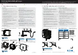
Fig. 92 3-4 Synchronizer And Third Gear
1 - 3-4 SYNCHRONIZER
2 - THIRD GEAR
Fig. 93 Geartrain Components
1 - SNAP RING
2 - FIFTH GEAR
3 - COUNTER GEAR
4 - BEARING
5 - LOCK BALL
6 - SYNCHRO HUB/SLEEVE
7 - SNAP RING
8 - SPACER
9 - COUNTER 5TH GEAR
10 - SYNCHRO RING
11 - 5TH SPLINE GEAR
12 - SNAP RING
21s - 30
MANUAL-AX5
TJ
OUTPUT SHAFT (Continued)
Summary of Contents for 2001 Wrangler TJ
Page 5: ......
Page 15: ......
Page 73: ......
Page 103: ......
Page 119: ......
Page 120: ......
Page 121: ......
Page 122: ......
Page 123: ......
Page 124: ......
Page 125: ......
Page 126: ......
Page 127: ......
Page 128: ......
Page 129: ......
Page 130: ......
Page 131: ......
Page 132: ......
Page 133: ......
Page 134: ......
Page 135: ......
Page 137: ......
Page 138: ......
Page 139: ......
Page 140: ......
Page 141: ......
Page 142: ......
Page 143: ......
Page 144: ......
Page 145: ......
Page 147: ......
Page 148: ......
Page 149: ......
Page 150: ......
Page 151: ......
Page 152: ......
Page 153: ......
Page 154: ......
Page 155: ......
Page 156: ......
Page 157: ......
Page 158: ......
Page 159: ......
Page 161: ......
Page 163: ......
Page 164: ......
Page 165: ......
Page 167: ......
Page 168: ......
Page 169: ......
Page 171: ......
Page 172: ......
Page 173: ......
Page 174: ......
Page 175: ......
Page 176: ......
Page 177: ......
Page 178: ......
Page 179: ......
Page 180: ......
Page 181: ......
Page 182: ......
Page 183: ......
Page 184: ......
Page 185: ......
Page 186: ......
Page 187: ......
Page 188: ......
Page 189: ......
Page 191: ......
Page 193: ......
Page 194: ......
Page 195: ......
Page 197: ......
Page 198: ......
Page 199: ......
Page 200: ......
Page 201: ......
Page 202: ......
Page 203: ......
Page 204: ......
Page 205: ......
Page 207: ......
Page 208: ......
Page 209: ......
Page 211: ......
Page 212: ......
Page 213: ......
Page 215: ......
Page 216: ......
Page 217: ......
Page 219: ......
Page 220: ......
Page 221: ......
Page 222: ......
Page 223: ......
Page 224: ......
Page 225: ......
Page 227: ......
Page 228: ......
Page 229: ......
Page 231: ......
Page 233: ......
Page 234: ......
Page 235: ......
Page 236: ......
Page 237: ......
Page 238: ......
Page 239: ......
Page 240: ......
Page 241: ......
Page 243: ......
Page 244: ......
Page 245: ......
Page 246: ......
Page 247: ......
Page 248: ......
Page 249: ......
Page 250: ......
Page 251: ......
Page 253: ......
Page 254: ......
Page 255: ......
Page 256: ......
Page 257: ......
Page 259: ......
Page 260: ......
Page 261: ......
Page 263: ......
Page 264: ......
Page 265: ......
Page 266: ......
Page 267: ......
Page 268: ......
Page 269: ......
Page 315: ......
Page 347: ...Fig 1 HEADLAMP SPLICES 8Wa 95 4 8W 95 SPLICE LOCATIONS TJ SPLICE LOCATIONS Continued ...
Page 348: ...Fig 2 RIGHT HEADLAMP SPLICES TJ 8W 95 SPLICE LOCATIONS 8Wa 95 5 SPLICE LOCATIONS Continued ...
Page 355: ...Fig 13 INSTRUMENT PANEL RHD 8Wa 95 12 8W 95 SPLICE LOCATIONS TJ SPLICE LOCATIONS Continued ...
Page 356: ...Fig 14 DASH PANEL LHD TJ 8W 95 SPLICE LOCATIONS 8Wa 95 13 SPLICE LOCATIONS Continued ...
Page 357: ...Fig 15 DASH PANEL RHD 8Wa 95 14 8W 95 SPLICE LOCATIONS TJ SPLICE LOCATIONS Continued ...
Page 358: ...Fig 16 BODY WIRING SPLICES TJ 8W 95 SPLICE LOCATIONS 8Wa 95 15 SPLICE LOCATIONS Continued ...
Page 359: ...Fig 17 REAR LAMPS 8Wa 95 16 8W 95 SPLICE LOCATIONS TJ SPLICE LOCATIONS Continued ...
Page 367: ......