


JDM
®
CD/USB/FM-RDS Receiver Module
3
Step 5:
Connect antenna module to the antenna header in the
main tuner module. See photo:
Step 6:
Attach the antenna module to the rear panel using the
self tapping screws provided.
Step 7:
Connect antenna to antenna module on rear panel. See
figure 3 and 4 for examples of FM and AM
antenna wiring.
INSTALLATION INSTRUCTIONS A 4320 - A 4324
JDM
ʻ
TA
ʼ
SERIES
AMPLIFIERS
Warning:
Before commencing installation ensure amplifier is
disconnected from power socket.
Step 1:
Open the cover of the amplifier and unscrew the blank
panel located on the front of the amplifier.
Step 2:
Locate the punchout panel marked “FM 75
Ω
” on the
rear panel and remove it. You may need to cut the panel sup-
ports with some heavy duty cutters or a small saw.
Step 3:
A fly lead and header will be taped to the back of the
front blank panel. Remove the tape and connect this lead to the
Power/Signal header on the tuner module. See photo:
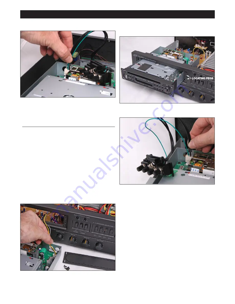
Step 4:
Insert module into amplifier and screw to front panel.
Ensure the plastic locating pegs on the module panel fit into the
amplifier front panel correctly. See photo:
Step 5:
Connect antenna module to the antenna header in the
main tuner module. See photo:
Step 6:
Attach the antenna module to the rear panel using the
self tapping screws provided.
Step 7:
Connect antenna to antenna module on rear panel. See
figure 3 and 4 for examples of FM and AM
antenna wiring.