


JDM
®
CD/USB/FM-RDS Receiver Module
2
FEATURES:
Receiver Section:
• Digital electronic analogue tuner AM/FM bands
• Radio Data System (RDS) function for FM radio
• 24 station preset memories (FM:18; AM:6)
• Manual or Scan (Seek) tuning, up and down
CD Section:
• Play/Pause button.
• Repeat and Random playback.
• Intro Scan play.
• Cue/Review function.
• Track skip and seek function.
• USB socket for USB stick.
IN THE BOX:
• CDR-100RDSU includes CD Player / AM and FM RDS Radio
Tuner / USB module.
• Antenna Terminal module – to insert into the PA Amplifier rear
panel and allow AM and FM antenna wiring to be connected.
• 300
Ω
balanced FM cable.
• Screws to attach module to PA system.
SUITABLE
FOR:
This module is designed to be used as an accessory to the JDM
PA amplifier products:
JDM
ZA-6120 (Altronics code: A 4330)
JDM
ZA-6240 (Altronics code: A 4332)
JDM
ZA-6480 (Altronics code: A 4336)
JDM
TA-1060 (Altronics code: A 4320)
JDM
TA-1120 (Altronics code: A 4322)
JDM
TA-1240 (Altronics code: A 4324)
INTERNAL
CONNECTIONS:
Before commencing installation, familiarise yourself with the
location of the Antenna and Power/Signal headers as shown in
Figure 1.
Figure 1:
Location of antenna and power/signal headers.
ANTENNA
POWER
& SIGNAL
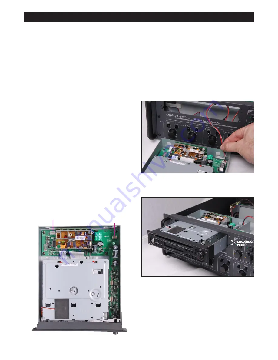
Step 4:
Insert module into amplifier and screw to front panel.
Ensure the plastic locating pegs on the module panel fit into the
amplifier front panel correctly. See photo:
INSTALLATION INSTRUCTION
FOR A 4330 - A 4336 JDM
ʻ
ZA
ʼ
SERIES
AMPLIFIERS
Warning:
Before commencing installation ensure amplifier is dis-
connected from power socket.
Step 1:
Open the cover of the amplifier and unscrew the blank
panel located on the front of the amplifier.
Step 2:
Locate the punchout panel marked “FM 75
Ω
” on the rear
panel and remove it. You may need to cut the panel supports
with some heavy duty cutters or a small saw.
Step 3:
A fly lead and header will be taped to the back of the
front blank panel. Remove the tape and connect this lead to the
Power/Signal header on the tuner module. See photo: