JCM Neptune Instruction Manual Download Page 15

15

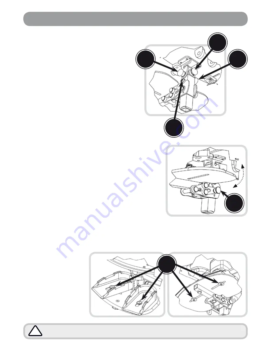
Legrest Detachment / Attachment 

• 

Pull and lock open plunger A1 (by rotating 

90°) which is on the right hand side of the 

seat as you are looking at the chair. 

• 

Pull and hold open the plunger A2 which is 

(on the left side of the seat as you are looking 

at the chair) to enable you to disengage the 

legrest from the main seating unit.

Legrest Length (3 positions)

• 

Hold open plunger (B) on the back 

of the leg rest post and re-locate into 

one of the holes in the legrest stem.

Footplate Angle / Flip Away

• 

Using plungers (C) on either side of 

the chair, select the relevant hole and 

release the plungers into the hole to 

secure the footplate in place.

• 

The footplate can be flipped up manually to 

allow clearance for standing transfers etc.

Footplate Height / Length

• 

Loosen bolt (D) by half a turn with a 4mm allen 

key so you can slide the footplate up and down 

the leg stem.

Note: For the shortest length raise the footplate 

up the leg stem to the minimum and close the leg 

stem to the minimum setting.

Sandal Fixing

• 

Underneath the footplate loosen the central 

allen key bolt turning anti-clockwise. 

• 

Rotate the sandal to the desired position along 

slot (E). 

• 

Fix in place by tightening the allen key bolt 

beneath the footplate

Do not use foot straps unless the client is wearing shoes. 

!

Legrest, Footplate & Sandal Adjustment

Foot Straps 

Foot straps or ankle 

supports can be attached 

through the slots in the 

sandal to secure feet. 

Feed the strap through the 

buckle and close the buckle 

shut to secure. Alternatively 

a fixing kit can be supplied 

to fit the ankle supports 

directly to the footplate.

E

A

1

A

2

B

D

C

View from 

back of seat

Summary of Contents for Neptune

Page 1: ...1 Neptune INSTRUCTION MANUAL...

Page 2: ...ained For further information please do not hesitate to contact us all contact details are on the back cover of the manual Thank you for purchasing our product we hope you enjoy your new seating syste...

Page 3: ...tions If you have been supplied the seating system with a JCM base frame please refer to the separate instruction manual relating to the specific base you have All of the upholstery is fitted with pre...

Page 4: ...future To use Turn the lever handle clockwise to tighten or anti clockwise to loosen To use the lever when an obstruction is met Pull the handle of the lever outwards towards you A This disables the f...

Page 5: ...ces them in an open position C LOCKED TURN OPEN A C B To close Turn the plungers a half turn clockwise and they should snap back into a locked position A Lever Use Using Index Plungers Operating Brake...

Page 6: ...ating system and should therefore be checked before issue If at any time it is noted that areas of the users skin remain reddened after being out of the seating system for around 10 minutes urgently c...

Page 7: ...ove the pommel when transferring the user in and out of the seat not required for contoured seats Foot Sandals and Straps Should only be fixed when the user is wearing shoes or boots Tray Do NOT use t...

Page 8: ...offer your child both comfort and support If the childs clothing has been adjusted i e a jumper removed the straps should be re adjusted accordingly Fixing Onto Chair The straps at the top of the har...

Page 9: ...for measuring hip width is from trochanter to trochanter If this is not possible measure from ASIS to ASIS and add a couple of inches The correct belt size for the individual has padding that covers a...

Page 10: ...when an adjustment has been made to the size of the system a stability assessment should be carried out prior to use of the equipment Always ensure that the back is secure and that the levers are tigh...

Page 11: ...ay from the framework Loosen the allen key bolts A by a half turn with a 4mm allen key supplied Move the sacral plate up or down within the adjustment slot Once in place tighten bolts A to secure Pad...

Page 12: ...er B outwards away from the arm While holding the plunger open tilt the arm up or down to achieve the angle required When a suitable position has been acquired lock the arm into place by releasing the...

Page 13: ...ioning of the user Loosen the levers by turning anti clockwise Once loose the head support angle can be manually adjusted to suit the user Tighten the levers to secure in place Adjusting the Headrest...

Page 14: ...ay C B Hip Pad Adjustment Hip Pad Width Un tighten allen key bolt A by a half turn using the 4mm allen key supplied Then slide the hip pad along the hip pad bar B to set at the desired width Re tighte...

Page 15: ...nding transfers etc Footplate Height Length Loosen bolt D by half a turn with a 4mm allen key so you can slide the footplate up and down the leg stem Note For the shortest length raise the footplate u...

Page 16: ...k there are no signs of failure in joints and welds Checktightness securityofallfixings bolts nuts springloadedpegs otherfitments Check for signs of fatigue wears replace parts that show signs of wear...

Page 17: ...endants Unauthorised modifications will also invalidate the warranty Any new parts required should be genuine JCM Seating Solutions Ltd approved parts fitted to JCM specifications Frequency of Service...

Page 18: ...a claim JCM reserve the right to inspect the product and all necessary documentation Only valid for products purchased after 1st April 2006 Applies only to certian products exclusively manufactured by...

Page 19: ...up to date Records on the new user must be updated to maintain traceability Inspection The equipment should have a rigorous inspection prior to the reissue to include the points covered in the six mon...

Page 20: ...b 2011 15 18 Maxwell Road Woodston Industrial Estate Peterborough Cambridgeshire PE2 7HU Tel 01733 405830 Fax 01733 405838 Email enquiries jcmseating co uk 2011 JCM Seating all rights reserved www jcm...

Reviews: