


P/N 960-100929R_Rev. 7 {EDP #148849}
© 2017, JAPAN CASH MACHINE CO., LTD.
6 - 8
Section 6
iVIZION® SeriesNext-Generation Banknote Acceptor Unit
Calibration and Testing
7. Click on the “
Start
a
)
to begin the following three (3) sequential Sen-
sors Calibration Procedures:
-
Cash Box Sensor
-
Nearly Full Sensor
-
Feed-Out Sensor
Calibration will be performed in the above order
while one of either “
Box RUNNING
”, “
Nearly
Full RUNNING
” and “
Feed-Out RUNNING
”
messages is showing on the Screen (Figure 6-33).
Once the three (3) Sensor Calibration Procedures
are complete, the “
Calibration Information
”
Screen shown in Figure 6-35 will appear.
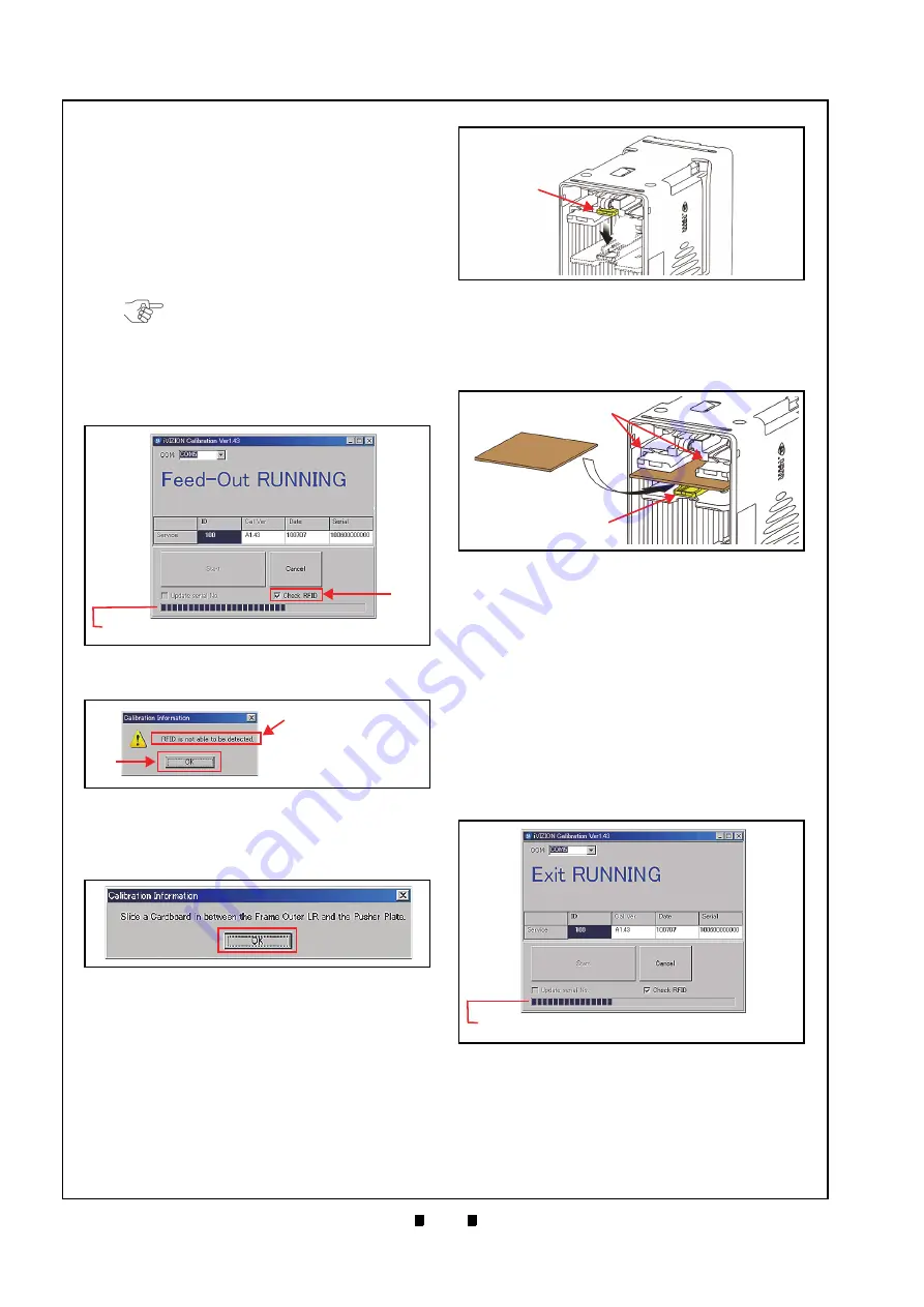
8. Remove the Cash Box to set the Pusher Plate for
the Home Position Sensor Calibration Procedure.
9. Open the Cash Box and press down on the Pusher
Release Plate (Figure 6-36
a
&
b
).
10. Hold the Pusher Plate down (Figure 6-37
a
) and
slide a 80x50mm piece of Cardboard (Figure 6-37
b
) in between the Frame Outer LR Guides (Figure
c
) and the Pusher Plate.
11. Reseat the Cash Box back into its Frame position.
12. Click on the “
OK
” Screen Button (Review Figure
a
) to begin the following four (4) Sensor
Calibration Procedures:
-
Home Position Sensor
-
Feed-In Sensor
-
Entrance Sensor
-
Exit Sensor
Calibration will be performed in the above order
while one of “
Home Position
RUNNING
”, “
Feed-In
RUNNING
”, “
Entrance
RUNNING
” or “
Exit
RUNNING
” messages is
showing on the Screen (Figure 6-38).
Once the four (4) Sensors Calibration Procedures
are complete, the “
Calibration Information
”
Screen shown in Figure 6-39 will appear.
NOTE: If the “Check RFID” Check-box
shown in Figure 6-33
is unchecked,
the “
Calibration Information
” Screen
shown in Figure 6-34 will appear.
When present, click on the “OK”
Screen Button (Figure 6-34
a
) to begin
the Calibration Procedure.
Feed-Out Calibration Proceeding
Figure 6-33
Feed-Out Calibration Proceeding
Screen
a
NOTE: The Barograph does not indicate a Calibration in progress.
Calibration Information Screen 1
Figure 6-34
Calibration Information Screen 1
a
dialogue box is different
depending on the Software
Version but procedure is
same.
Calibration Information Screen 2
Figure 6-35
Calibration Information Screen 2
a
Figure 6-36
Pusher Plate Release Location
a
b
Figure 6-37
Figure 6-37
Cardboard Setting Location
a
a
b
Slide In
Cardboard
Figure 6-38
Exit Calibration Proceeding Screen
NOTE: The Barograph does not indicate a Calibration in progress.


