background image

28


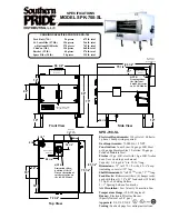
The supplied calibration microphone must be connected to perform RMC. If the RMC 

button is pressed and held for 3 seconds or longer and no mic is connected, the meter 
display will flash to indicate an error condition, and all RMC settings currently in memory will 
be erased.  

RMC error condition

To bypass the calibrated settings and compare the original, uncompensated performance with 
the corrected performance, press the RMC button so that it lights up. This allows you to listen 
to the speaker without the filter, delay, level trim and meter calibration applied during the 
RMC process.  To restore RMC functions, press the button again. The button will no longer be 
illuminated.

Equalization

Equalization is provided to tailor response to preference, or acoustic conditions in the room.  
The LSR4300 offers two bands of onboard digital equalization (high and low frequency), 
with up to 2 dB of cut and boost in each band.  The equalization is shelving type with centers 
of 500 Hz for low frequency and 2 kHz  for high-frequency. Using the supplied LSR4300 
Control Center software, the corner frequency for each band is adjustable from 20 Hz to 1 kHz 
(LF) and 1 kHz and 20 kHz (HF).

To turn equalization on, press the EQ button on any networked speaker so that it lights up.  
The LF and/or HF buttons immediately to the right of the EQ button will also light up if the 
current setting contains LF or HF boost or cut.  (If the current EQ setting contains “flat” LF or 
HF equalization – that is, no boost or cut – the associated button will not light.)

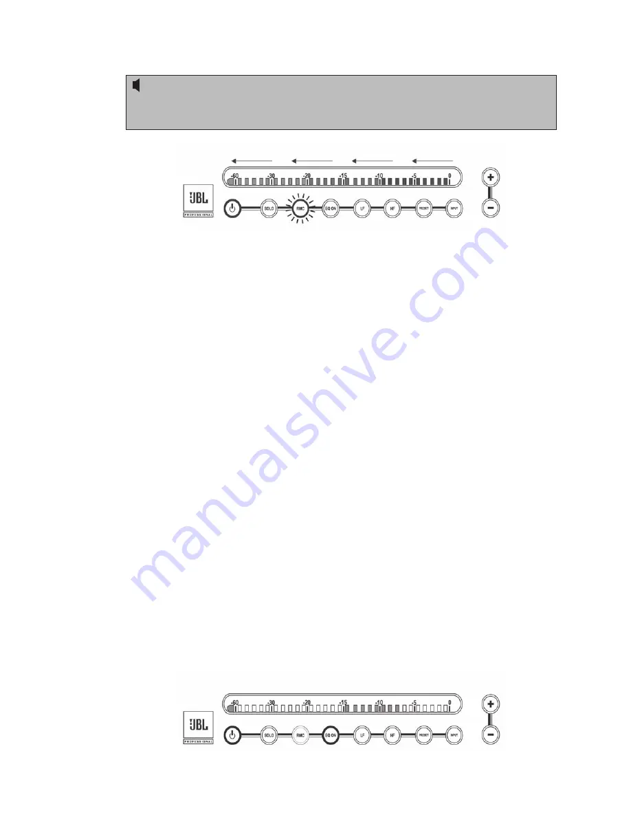
To apply equalization, simply press the LF or HF button (it will begin blinking), followed by 
the +/- buttons.  The meter display LEDs will light (all in green) to show you the amount of 
cut or boost.  If only the two LEDs on either side of the center (-15) mark are lit, that is an 
indication that the selected equalization band is flat (i.e., no cut or boost).  LEDs lit to the right 
of center (that is, to the right of the –15 mark) indicate the amount of equalization boost, while 
LEDs lit to the left of center (that is, to the left of the –15 mark) indicate the amount of  
equalization cut.  With every 0.25 dB of equalization boost or cut, an additional two LEDs 
light.  Thus, for example, an equalization boost of 1 dB is indicated by eight LEDs lit to the 
right of the center (-15) mark. 


Reference - Performing An RMC Calibration/Equalization

Summary of Contents for LSR4328P

Page 1: ...LSR4328P LSR4326P Studio Monitors Owner s Manual...

Page 2: ...ii...

Page 3: ...en into the apparatus the apparatus has been exposed to rain or moisture does not operate normally or has been dropped 15 The appliance coupler of the power supply cord is used as the ultimate disconn...

Page 4: ...on 24 Performing An RMC Calibration 25 Equalization 28 Restoring Factory Settings 30 LSR4300 Control Center Software 30 Appendix A EQ Presets 31 Appendix B System Block Diagram 33 Appendix C Wiring Re...

Page 5: ...nce you ve got your LSR4300 system powered up and delivering sound you should turn to the Reference section which describes every feature and function of the LSR4300 in detail Finally we ve included a...

Page 6: ...nt or worse yet lack of any treatment at all can result in anomalies such as resonant frequencies and low frequency standing waves the aural equivalent to the lens being smeared Trying to create a mix...

Page 7: ...HiQNet automatically aligns the entire system setting relative volume so that the sound from all channels is balanced when it arrives at the mix position The end result is precise imaging regardless o...

Page 8: ...All transducers are self shielded with Neodymium motor structures for exceptional transient response and superb power handling Advanced front panel user interface allows control of system functions s...

Page 9: ...teries Here are simple step by step instructions to get you up and running quickly 1 Unpack the speakers To avoid damage to the speaker elements open the top of the box keep the Styrofoam end cap on a...

Page 10: ...up ON position for the speaker reproducing the left channel and place the DIP switch labeled RIGHT in the up ON position for the speaker reproducing the right channel See page 22 in this manual for mo...

Page 11: ...reo setup Then use appropriate cabling to make a connection between the rear panel AES EBU XLR or S PDIF phono output of the left speaker and the rear panel AES EBU or S PDIF input of the speaker desi...

Page 12: ...on on any speaker then walk to a spot in the room where you are not blocking the path between the microphone and any speaker Each speaker will emit a reference tone in turn and its meter will show a l...

Page 13: ...AC power source indicating the speaker is in standby status It is illuminated at full brightness when the speaker is powered up and active Full brightness level is variable set using the brightness le...

Page 14: ...Overall system volume see 11 below Meter and button brightness see 11 below Error conditions The meter has 31 three color segments that can illuminate in green amber or red For many of the above opera...

Page 15: ...eter segments will ash to indicate a muted state To end solo and unmute all other networked speakers press the SOLO button for that speaker again All front panel button actions can be cancelled at any...

Page 16: ...on to activate LF EQ it will ash While ashing press the button to increase the amount of LF EQ in 0 25 dB steps or press the button to decrease the amount of LF EQ in 0 25 dB steps For more informatio...

Page 17: ...select and activate one of six factory EQ presets or a seventh current setting preset To recall a preset press the PRESET button It will ash While ashing use the or buttons to select the desired pres...

Page 18: ...ght goes out or by manually setting both the LF and HF values to 0 dB 10 INPUT Input Select Allows you to listen to any of three connected signal sources analog S PDIF digital or AES EBU digital To se...

Page 19: ...indicate the current selection When monitoring digital S PDIF or AES EBU signal the rear panel DIP switches must be set correctly in order to determine which channel is being reproduced For more infor...

Page 20: ...the Meter Display There are six settings at the lowest setting all buttons and meter segments are completely off and only the JBL logo glows to indicate power Rear Panel LSR4328P LSR4326P Rear Panel 1...

Page 21: ...nection when using the provided LSR4300 Control Center software 11 DIP switches These eight switches are used to identify the channel being carried by each speaker in a networked system If one of the...

Page 22: ...as power on volume adjust soloing input select EQ adjustment and preset selection and adds the following extra functions A dedicated brightness control System volume DIM function When a function is se...

Page 23: ...eaker 6 EQ controls a EQ ON Duplicates the function of the front panel EQ control b HF Duplicates the function of the front panel HF control c LF Duplicates the function of the front panel LF control...

Page 24: ...hey should be placed on suitable speaker stands and well away from boundaries such as walls ceilings and large pieces of furniture The LSR4328P and LSR4326P are equipped with mounting points to allow...

Page 25: ...single button with the supplied calibration microphone connected to a single speaker It also makes it possible for all speakers in the system to be controlled using the supplied wireless remote contro...

Page 26: ...e its LEFT DIP switch set to ON When using only a single speaker set the LEFT DIP switch to ON regardless of the speaker s physical position in the room If required LSR4300 monitors can be used withou...

Page 27: ...in the output acoustic level of 94 dB SPL at a distance of one meter Use of the front panel Volume control that is pressing the button when no button is ashing allows further level matching Incoming a...

Page 28: ...connections and 75 ohm cabling for S PDIF connections LSR4300 audio interconnections RMC Room Mode Correction When a loudspeaker is placed in any work space it and the room behave as a system which f...

Page 29: ...y useful in surround sound applications where space limitations often prevent optimum speaker placement For example if the center speaker is closer to the mix position than the other main speakers att...

Page 30: ...om the nearest speaker Position the calibration microphone vertically 3 Connect the microphone to the Left speaker s rear panel RMC MIC input To perform RMC the calibration microphone must be connecte...

Page 31: ...fairly loud swept sine wave calibration tone that can surprise you when you hear it for the rst time After pressing the RMC button move away from the speaker There is a ve second delay prior to the so...

Page 32: ...are the corner frequency for each band is adjustable from 20 Hz to 1 kHz LF and 1 kHz and 20 kHz HF To turn equalization on press the EQ button on any networked speaker so that it lights up The LF and...

Page 33: ...out of the preset function no change is made to the current settings LSR4300 Control Center software allows the creation and storage of custom user equalization curves which can then be loaded into m...

Page 34: ...s such as RMC and EQ remain stored in each speaker even when powered down For that reason if you are using an LSR4300 system that you did not personally set it s a good idea to restore factory setting...

Page 35: ...EQ Presets All factory EQ presets use an LF corner frequency of 500 Hz and a HF corner frequency of 2 0 kHz Preset 1 LF 0 dB HF 2 0 dB Preset 2 LF 1 5 dB HF 0 dB Preset 3 LF 2 0 dB HF 2 0 dB Appendix...

Page 36: ...32 Preset 4 LF 0 dB HF 1 dB Preset 5 LF 0 dB HF 2 dB Preset 6 LF 1 5 dB HF 0 dB Appendix A EQ Presets...

Page 37: ...33 Appendix B System Block Diagram Appendix B System Block Diagram...

Page 38: ...ible the cable shield should not be connected to any signal pin but left to perform a cable shielding function only Note Under no circumstances should the safety ground wire be removed from the AC pow...

Page 39: ...n unbalanced source connected to the balanced XLR input of the LSR monitor using twisted pair cable Note that the shield is connected to the GROUND SHIELD connector at the LSR input but not at the sou...

Page 40: ...he Ring of the Tip Ring Sleeve plug at the LSR4328P LSR4326P input Diagram E details the connections using unbalanced cable and Tip Sleeve connections to the 1 4 or XLR input Digital Audio Connections...

Page 41: ...ess of the mounting plate Hole Pattern Caution Unsafe mounting or overhead suspension of any heavy load can result in serious injury and equipment damage Mounting of speakers should be done by quali e...

Page 42: ...aying the pink noise source back through your LSR4300 speakers 3 Using the buttons raise the LSR4300 system volume so that the rst amber colored LED 10 dB begins to icker and note the amount registere...

Page 43: ...ront panel buttons blink and the meter shows 5 segments moving back and forth on the speaker showing the error Correct DIP switch settings Sync Signal Error No digital signal found or loss of sync sig...

Page 44: ...and cables Con rm you are using suitable cable of proper impedance If cables and connections are OK source may be unstable I am having trouble daisy chaining my digital audio through multiple speaker...

Page 45: ...version For example Firmware v1 1 will be displayed as follows Firmware v2 0 will be displayed as follows If your Studio Monitors have differing rmware versions download the latest version from JBL a...

Page 46: ...06 dB 1m Maximum Peak SPL 112 dB 1m Maximum Peak SPL Per Pair 118 dB SPL 1m Low Frequency Model 438H LSR4328P 436H LSR4326P Diameter 203 mm 8 in LSR4328P 159 mm 6 25 in LSR4326P Voice Coil 2 51 mm LSR...

Page 47: ...it RMC Microphone Input Use supplied microphone only 1 8 tip ring sleeve powered 15 Volts on tip Network Connection RJ45 IN RJ45 OUT Network Protocol Proprietary HiQNet Protocol using RS485 Computer I...

Page 48: ...ore selecting a mount ing bracket be certain that it is capable of supporting the weight of the speaker to be mounted Notes All measurements unless otherwise stated made anechoically in a 4p environme...

Page 49: ...ual damage resulting from the performance of repairs by someone not authorized by JBL claims based upon any misrepresentations by the seller any JBL product on which the serial number has been defaced...

Page 50: ...TO THE REPAIR OR REPLACEMENT AT OUR OPTION OF ANY DEFECTIVE PRODUCT AND SHALL NOT INCLUDE INCIDENTAL OR CON SEQUENTIAL DAMAGES OF ANY KIND SOME STATES DO NOT ALLOW LIMITA TIONS ON HOW LONG AN IMPLIED...

Page 51: ...ete list of JBL Professional international distributors is provided at our U S A website www jblpro com En Dehors des Etats Unis Contacter votre Distributeur JBL Professional Une liste compl te de nos...

Page 52: ...48 Part Number Rev 101305 352712 003 09 06...

Reviews: