


5
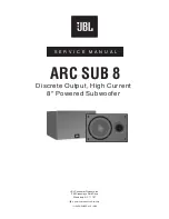
Powered Subwoofer
ARC SUB 8
1. TROUBLE SHOOTING BEFORE OPENING
Check connections, control settings, driver and other possible
external problems. If there is Output, determine if all controls
and Inputs function properly. Rotate Pots over full range while
applying lateral and vertical oscillating forces to locate possible
intermittent function. High Level Inputs should be tested
individually both differentially (signal from "-" to "+" with normal
output) and in common mode (signal from low level ground to
both "+" and "-" shorted together, giving virtually no output).
While passing a signal, corner drop the enclosure a few inches
to expose possible intermittent problems. Check woofer for
rubbing of voice coil or tears in cone or surround. Check
cabinet for loose extraneous articles which may have been
pushed into front port.
2. REMOVING THE AMPLIFIER.
There are voltages and hot components at many points in the
amplifier which can, if contacted, cause personal injury. Be
extremely careful. Any adjustments or service procedures that
require operation of the amplifier out of its enclosure should be
performed only by trained service personnel. Refer to PCB
drawings for locations of hazards and familiarize yourself with
their locations before starting.
A. Remove the subwoofer grille.
B. Remove the (4) 1 Black PPH screws attaching the
woofer to the cabinet.
C. Remove the woofer, unplug the two connecting
wires.
D. Remove the (8)
screws black pph screws
attaching the ampifier assembly to the cabinet.
E. Remove the ampifier assembly.
F. For access to the input panel, first remove the three
outer screws. Remove knob and nuts from
potentiometers. Cut away the sealant securing the
cover to the faceplate. The input PCB should now
pull out completely.
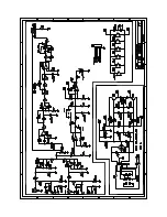
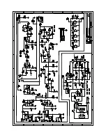
3. TROUBLE SHOOTING AFTER REMOVAL
Verify AC plug is disconnected. See WARNINGS in section 2.
To prevent loose hardware from reducing safety spacings, it is
essential that all hardware be replaced in the same manner as
it was removed, with lock washers under all nuts, proper torque
on screws and thread locking sealer on the transformer nuts.
If line core or strain relief are replaced, it is necessary to seal
them completely to panel with an approved conformal coating
to prevent air "whistling" through any openings from woofer
pressure.
To reduce the risk or electric shock and/or fire,
replace items as marked on schematic with the
safety marking only with the exact replacements
listed in the safety component list, section 4. If
exact replacements are not available, order them from the
factory or an authorized service center.
A.
Check fuse F1. If blown visually check transformer
for discoloration, and large capacitors (C1, C2) for
bulges or venting. Check for shorts with an
Ohmmeter, (see schematic).
B.
With ohmmeter, verify voice coil of woofer is
3.2 ohms, and windings of transformer are
continuous.
C. Examine board and wiring for obvious damage,
broken or poorly soldered connections, or
discoloration.
D. Repair or replace items identified above.
E. For live power testing, attach a 4 ohm 100 watt
resistor to the output wires.
F. If the LED is not on, check for fuse continuity and
then for cold solder joints on CMC1 and bridge
diode.
G. With a signal present at the input, the output to the
power amp is at pin #8 of U1. If the signal is not
present at pin 8, there is a problem with preamp
section. Most likely, a cold solder joint will be the
problem. Track back the signal path to locate
problem.
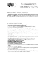
CAUTIONS AND WARNINGS
BEFORE THIS AMPLIFIER IS PLUGGED IN, make sure its rated voltage corresponds to the voltage of the AC power source
to be employed. Failure to use the correct voltage could cause damage to the amplifier when the AC power cable is
plugged in. Do not exceed the rated voltage by more than 10%; operation below 90% will degrade performance or cause the
unit to shut off.
Summary of Contents for 8
Page 8: ...7 Powered Subwoofer ARC SUB 8 ARC SUB 8 AMPLIFIER BLOCK DIAGRAM...
Page 9: ...8 Powered Subwoofer ARC SUB 8 CABINET EXPLODED VIEW...
Page 12: ...1 1 Powered Subwoofer ARC SUB 8 PACKAGING EXPLODED VIEW...
Page 13: ...1 2 Powered Subwoofer ARC SUB 8 INTEGRATED CIRCUIT DIAGRAM...
Page 14: ...1 3 Powered Subwoofer ARC SUB 8 PRINTED CIRCUIT BOARD TOP VIEW...