background image

3

Powered Subwoofer

ARC SUB 8

CONTROLS AND THEIR FUNCTION

1. Output Level - The Output Level adjustment

determines volume level strength.

2. Crossover Frequency - The Crossover Frequency

adjustment determines the highest frequency the

ARC SUB 8 will reproduce. It allows a seamless

transition from the subwoofer to the satellite

speakers.

3. On (LED) - This LED will light green when the unit is

plugged in and is receiving signal. When in

standby mode the LED is red.

4. Low Level Input - These left and right Line Level

Inputs are normally used when the

receiver/processor has line-level pre-amp out

or subwoofer out jacks.

5. High Level Inputs - These High Level Inputs are for

receivers that do not have line-level pre-amp out

or subwoofer out jacks. When a pair of main or

satellite speakers are attached to the OUTPUT

terminals, frequencies below 180 Hz are attenuated

by the high-pass filter.

Summary of Contents for 8

Page 1: ...N U A L JBL Consumer Products Inc 250 Crossways Park Drive Woodbury N Y 11797 A Harman International Company 1112 ARCSUB8 Rev A 10 98 S E R V I C E M A N U A L ARC SUB 8 Discrete Output High Current 8...

Page 2: ...high polymer laminated cone Inputs Line level and High Level Outputs High level with High Pass filter at 180Hz Crossover Frequency 50 150Hz continuosly variable Frequency Response 45Hz to 150Hz deter...

Page 3: ...ANTIES OF MERCHANTABILITY AND FITNESS FOR A PARTICULAR PURPOSE EXCLUSIVE REMEDIES THE REMEDIES PROVIDED HEREIN ARE BUYER S SOLE AND EXCLUSIVE REMEDIES THE MANUFACTURER SHALL NOT BE LIABLE FOR ANY DIRE...

Page 4: ...D This LED will light green when the unit is plugged in and is receiving signal When in standby mode the LED is red 4 Low Level Input These left and right Line Level Inputs are normally used when the...

Page 5: ...signal generator 7 Turn on generator and adjust so that speaker level output is 2 0V 50 Hz Turn VOLUME control full clockwise 8 Green LED should light immediate bass response should be heard and felt...

Page 6: ...INGS in section 2 To prevent loose hardware from reducing safety spacings it is essential that all hardware be replaced in the same manner as it was removed with lock washers under all nuts proper tor...

Page 7: ...one of the following methods A Insulation Resistance Test With a 500VDC Insulation Tester Check insulation from the outer metal contact of the RCA jack chassis to the line neutral of AC cord Resistanc...

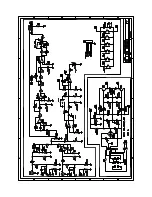
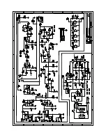
Page 8: ...7 Powered Subwoofer ARC SUB 8 ARC SUB 8 AMPLIFIER BLOCK DIAGRAM...

Page 9: ...8 Powered Subwoofer ARC SUB 8 CABINET EXPLODED VIEW...

Page 10: ...W 5 1 3W CAN BE USED R11 12 40100 330 1 2W 5 2 CARBON FILM R10 13 40404 1K 2W 5 2 CARBON FILM Ref Part Description Qty R14 20 40405 4 7K 1 4W 5 2 CARBON FILM R16 17 40101 820 2W 5 2 CARBON FILM R18 40...

Page 11: ...BS FOR CONTROLS 2 F1 80104 250V 0 50A T TYPE SLO BLO FUSE 1 POWER CORD 80105 POWER CORD 2 CONDUCTOR 1 STRAIN RELIEF 70305 POWER CORD STRAIN RELIEF 1 FUSE PCB 80106 PCB COMPLETE WITH CONNECTORS 1 FACEP...

Page 12: ...1 1 Powered Subwoofer ARC SUB 8 PACKAGING EXPLODED VIEW...

Page 13: ...1 2 Powered Subwoofer ARC SUB 8 INTEGRATED CIRCUIT DIAGRAM...

Page 14: ...1 3 Powered Subwoofer ARC SUB 8 PRINTED CIRCUIT BOARD TOP VIEW...

Page 15: ...1 4 Powered Subwoofer ARC SUB 8 SCHEMATIC DIAGRAM 1 5 5 4 4 3 3 2 2 1 1 A A B B C C D D E E F F G G S53AMI U2 T1...

Page 16: ...1 5 Powered Subwoofer ARC SUB 8 5 5 4 4 3 3 2 2 1 1 A A B B C C D D E E F F G G U1a U1d U1b U1c 2N3906 100K 6 04K 150K SCHEMATIC DIAGRAM 2...

Reviews: