40 mm
50 mm
60 mm
80 mm
100 mm
130 mm
130 mm
para manuales - color gris
200 mm
300 mm
PCB PLACEMENT 1
PCB PLACEMENT 2
PCB PLACEMENT 3
1
2
3
1
2
3
1
2
3
1
2
3
1
2
3
1
2
3
1
2
3
1
2
3
1
2
3
1
2
3
1
2
3
PCB PLACEMENT 1
PCB PLACEMENT 2
PCB PLACEMENT 3
1
2
3
1
2
3
1
2
3
1
2
3
1
2
3
1
2
3
1
2
3
1
2
3
1
2
3
1
2
3
1
2
3
1
3
4
6
7
9
2
5
8
40 mm
50 mm
60 mm
80 mm
100 mm
130 mm
130 mm
para manuales - color gris
200 mm
300 mm
9
Keep lifting the holder until it is in a vertical position (3).
Then tilt the holder all the way to the desired angular position (4) and insert the studs of the positioning
levers in the desired position to fix the holder in place (5).
.
The PCB is now turned around by 180º and the top side of the PCB is facing down.
Proceed in reverse order if you want to work on the top side of the PCB again.
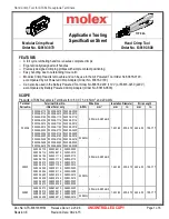
PCB Placement
Loosen the knobs of the spring guide clamps (1), adjust their distance according to the PBC width (2)
and tighten the knobs again. Clamps that are not needed can be slided to the side (3) (or disassembled).
Loosen the knobs of the sliding guide clamps (4) and slide unneeded clamps aside (5).
Insert the PCB into the slots of the spring guide clamps (6) and into at least one slot clamp on the side
of the sliding guide (7) and tighten the clamp knob (8).
Press the sliding guide against the PCB to move it together with the spring guide slightly backwards
(9) until the sliding guide clicks into place.
Sliding guide
clicks into place
Spring Guide
Sliding Guide