


ENGLISH
USER MANUAL
JB SYSTEMS®
5/12
EZ-CON 192
32. [DMX OUTPUT]:
Sends DMX-signals to the connected fixtures
33. [M-DMX OUTPUT]:
Please note that this USB-connector is NOT used for updates or to connect the
unit to a PC! Instead this USB-connector makes it very easy to add wireless DMX to the unit! Just
add the (optional) WTR-DMX DONGLE from BRITEQ
®
and you will get wireless DMX! No extra
settings to be made in the setup menu, just follow the procedure in the user manual supplied with
the WTR-DMX DONGLE from BRITEQ
®
. The separate WTR-DMX DONGLE is available from
WWW.BRITEQ-LIGHTING.COM (order code: B04645)
34. USB A-PORT:
Used to insert a memory stick for recording the programmed shows. Can also be
used to put in a USB LED light (5V)
35. POWER SWITCH:
Used to switch the unit ON/OFF
36. MAINS INPUT:
with IEC14 socket and integrated fuse holder, connect the supplied mains cable
here.
SET UP
1. [FIXTURE SETUP]:
The EZ-CON 192 has 12 [FIXTURES] (1)
buttons”. Each fixture button
represents 16 DMX channels. (8 faders on page A and 8 faders on page B)
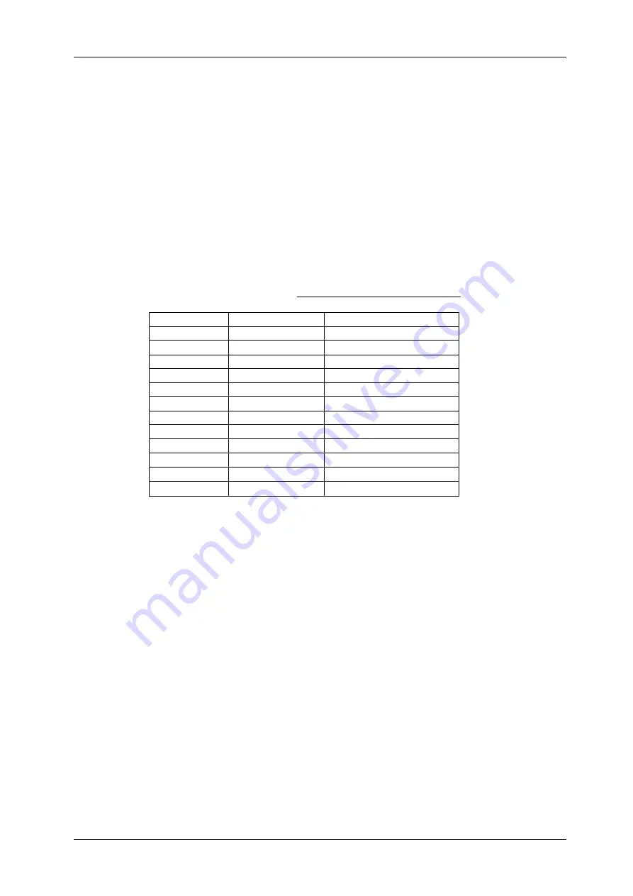
The following chart helps you to set up the DMX-start address on your fixtures:
Fixture #
Digital Setting
Dip Switch Setting
1
1
1
“On”
2
17
1 and 5 “On”
3
33
1 and 6 “On”
4
49
1,5 and 6 “On”
5
65
1 and 7 “On”
6
81
1,5 and 7 “On”
7
97
1,6 a
nd 7 “On”
8
113
1,5,6 and 7 “On”
9
129
1 and 8 “On”
10
145
1,5 and 8 “On”
11
161
1,6 and 8 “On”
12
177
1,5,6 and 8 “On”
2. [JOGWHEEL SETUP]:
For each fixture any 2 addresses can be assigned to the PAN (19) and TILT
(18) jogwheels:
•
Press and hold the [PROGRAM] (25) button until its LED blinks.
•
Press 2 times the [MODE] (21) and [FINE] (20) buttons at the same time. The assign LED (10)
should light up. (if reverse LED (22) is lit, press both buttons a second time together)
•
Use the [BANK
▲] (14) and [BANK ▼] (14) buttons to select the axis you wish to assign (PAN or
TILT).
•
If your fixture has more than 8 DMX addresses, you can use the [TAP/DISPLAY] (16) button to
select 16 or 8 channel mode.
•
Press the button (1) corresponding to the fixture you wish to edit.
•
While holding the [MODE] (21) button press the scene number (6) corresponding to the fader
which controls the movement. (Example: If PAN is controlled by fader number 4, press and hold
the [MODE] (21) button while pressing scene (6) button 4).
•
When both PAN and TILT are assigned, press the [MODE] (21) and [FINE] (20) buttons at the
same time again to exit ASSIGN mode.
Note:
you can still use the channel faders instead of the jog wheels to control the movements of the
fixture.
1. DELETE JOGWHEEL SETUP FOR A FIXTURE:
•
Enable Programming Mode. (Press and hold the [PROGRAM] (25) button until its LED blinks)
•
Press 2 times the [MODE] (21) and [FINE] (20) buttons at the same time. The ASSIGN LED (10)
should light up. (if the REVERSE LED (22) is lit, press both buttons a second time together)
•
If your fixture has more than 8 DMX addresses, you can use the [TAP/DISPLAY] (16) button to
select 16 or 8 channel mode.


