background image

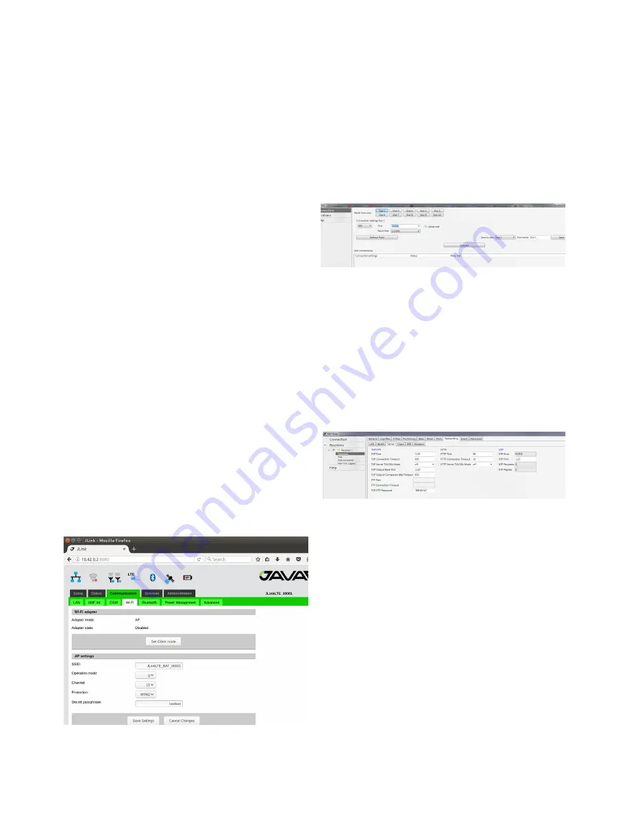
In the Communication/WiFi tab click on the 

“Set AP mode” to switch the interface to the 

AP mode and set following AP parameters: 

SSID (WiFi Accesses pointname), Protection 

(WPA2) and Security passphrase  (“pass-

word”) .
In the Communication/Power Management 

tab turn the WiFi interface on.
The detailed connection status you can check 

in the Status/WiFi tab. Here HPT404BT JL 

provides port forwarding mechanism from 

internet (GSM interface) to WiFi clients.
The port forwarding mechanism works in a 

following way: HPT404BT JL receives data 

from internet and redirects it to its WiFi cli-

ents. Data packets received by 1110-1119 

ports will be redirected to Wi-Fi. 
WiFi client which IP address is 10.1.10.110. 

Data packets received by 1120-1129 ports will 

be redirected to WiFi client which IP address 

is 10.1.10.120.
To receive the redirected data of HPT404BT 

JL the TRIUMPH-2 unit should be connected 

to HPT404BT JL through WiFi interface 

and TRIUMPH-2’s IP address should be set 

to 10.1.10.110 or 10.1.10.120  (the default 

gateway is 10.1.10.1).

Figure 24.  HPT404BT JL WiFi configuration tab

TRIUMPH-2 configuration steps are the 

following:
1. Connect TRIUMPH-2 to PC via USB or Blue-

tooth interface and start NetView&Modem.
2. Click Connection, select the port, specify 

the COM port the receiver is connected to. 

Click Connect to connect to the receiver.

Figure 25.  NetView connection tab

3. Select the receiver from the list of the con-

nected receivers and click Parameters/Net-

working/Server , to setup Service port.

•  Set the TCP/FTP parameter: TCP Port 

(1125).

•  Set the TCP/FTP parameter: TCP Out-

put Base Port (1120).

•  Click Apply.

Figure 26.  NetView Server tab

4. Select the receiver from the list of the con-

nected receivers and click Parameters/Net-

working/WLAN, to setup the WiFi connec-

tion.
Set the following IP parameters: WLAN Re-

ceiver IP Address(10.1.10.120), WLAN De-

fault Gateway (e.g, 10.1.10.1), and WLAN Net-

work Mask (e.g, 255.255.255.0).
 Set the AccessPoint parameters: WLAN Ac-

cess Point ID (enter SSID of HPT404BT JL), 

WLAN AP mode(wpa).
Set the WPA parameter: WLAN WPA Pass-

15

HPT404BT JL USER MANUAL

Summary of Contents for HPT404BT JL

Page 1: ...User Manual All contents in this manual are copyrighted by JAVAD GNSS All rights reserved The informa tion contained herein may not be used accessed copied stored dis played sold modified published o...

Page 2: ...e veloped by the expenditure of considerable work time and money and are the result of original selection coordination and arrange ment by JAVAD GNSS TRADEMARKS HPT404BT JL JAVAD GNSS are trademarks o...

Page 3: ...disclosing Confidential Information to your employees as may be necessary or appropriate to operate or care for HPT404BT JL Such employees must also keep the Confidentiality Information con fidential...

Page 4: ...he use of the symbol indi cates that this product may not be treated as household waste By ensuring this product is disposed of correctly you will help prevent potential negative consequences for the...

Page 5: ...field GNSS equipment to RTN where no cell phone cover is available HPT404BT JL de vices may contain 4 W UHF 406 to 470 MHz DESCRIPTION AND OPERATION radio transceiver HPT404BT JL can be configured an...

Page 6: ...oduction of hazards when operating and installing before connecting of the equipment to the supply make sure that the sup ply meets local and national safety ordinances and matches the equipment s vol...

Page 7: ...na 450 455 MHz 5 8 5 dBd gain NMO UHF Antenna 455 460 MHz 5 8 5 dBd gain NMO UHF Antenna 460 465 MHz 5 8 5 dBd gain NMO UHF Antenna 465 470 MHz 5 8 5 dBd gain NMO provide better gain but to achieve th...

Page 8: ...terfaces are available Ethernet Configure Ethernet interface in the Communication LAN tab Set the network parameters and reboot the device using Re boot button in the Administration Manage ment tab se...

Page 9: ...to setup with following pa rameters Baudrate 115200 Parity none Data Bits 8 Stop Bits 1 Handshake hardware Figure 7 Advanced configuration tab Access to Serial port via Network In the Communication Ad...

Page 10: ...cover is for micro SIM the second slot is for micro SD In the Communication Power Management tab activate the GSM interface Figure 10 HPT404BT JL Power Management tab Wait for registering in the netwo...

Page 11: ...er tab se lect following parameters NTRIP Client as Source and Serial port as Destination Click Save Setting button and wait until finish Figure 14 HPT404BT JL NTRIP Data Router tab 6 Setup NTRIP Clie...

Page 12: ...HPT404BT JL to provide RTK data received via UHF channel in Satel mode to Serial Port The following are the steps of configuration of HPT404BT JL 1 Connect to HPT404BT JL via web interface as describ...

Page 13: ...select Serial port as parameter as Terminal Click Save Setting button and wait until finish Figure 20 HPT404BT JL Advanced tab 4 Reboot device In the Administration Management tab click Reboot button...

Page 14: ...UMPH 2 connected to HPT404BT JL as a WiFi client The following are the steps of configuration of HPT404BT JL 1 Connect to HPT404BT JL via web interface 2 GSM configuration In the Communication GSM tab...

Page 15: ...2 s IP address should be set to 10 1 10 110 or 10 1 10 120 the default gateway is 10 1 10 1 Figure 24 HPT404BT JL WiFi configuration tab TRIUMPH 2 configuration steps are the following 1 Connect TRIU...

Page 16: ...NetView WLAN configuration tab After restarting the device you can check the WiFi connection in the web interface Status WiFi tab of HPT404BT JL Figure 28 HPT404BT JL WiFi status tab Now TRIUMPH 2 ca...

Page 17: ...B and 3 0dB under extreme test conditions Carrier Frequency Stability 1 5 ppm initial stability over temp with 3 0 ppm aging year Max Frequency Error 1 0 kHz at normal test conditions 1 5 kHz under ex...

Page 18: ...O Release A Up to 3 1 Mbps forward channel Up to 1 8 Mbps reverse channel CDMA IS 2000 Up to 153 kbps simultaneous forward and reverse channels UMTS WCDMA HSDPA HSUPA HSPA DC HSPA Bands 1 2100 MHz 2 1...

Page 19: ...a RS 232 12 DSR_IN I Data Set Ready RS 232 13 DCD_OUT O Data Carrier Detect RS 232 14 USB0_VBUS PWR Power line USB 15 USB0_ID I USB0 ID line 16 ETD O Transmit Data negative line LAN 17 ERD I Receive D...

Page 20: ...damaged in any way such as power supply cord or plug is damaged liquid has been spilled or objects have fallen into the apparatus or has been dropped Apparatus shall not be exposed to dripping or spl...

Page 21: ...epair damage to the product resulting from an accident disaster misuses abuse or modification of the prod uct Warranty service may be obtained from an authorized JAVAD GNSS warranty service dealer If...

Page 22: ...900 Rock Avenue San Jose CA 95131 USA Phone 1 408 770 1770 Fax 1 408 770 1799 www javad com All rights reserved JAVAD GNSS Inc 2018...

Reviews: