background image

Contents


INTRODUCTION ......................................................................... 3


FEATURES AND SPECIFICATIONS ......................................... 4


SYSTEM REQUIREMENT .......................................................... 7


CHECK LIST ............................................................................... 8


HARDWARE DESCRIPTION...................................................... 8


DISPLAY DEVICES OUTPUT .................................................. 10


HARDWARE INSTALLATION.................................................. 11


I

NSTALLATION 

P

ROCEDURES

........................................................ 11


S

TEPS

: ........................................................................................ 12


SOFTWARE INSTALLATION................................................... 13


á


W

INDOWS

®


XP


D

RIVER 

I

NSTALLATION

.................................. 13


á


W

INDOWS

®


2000


D

RIVER 

I

NSTALLATION

.............................. 15


TECHNICAL ASSISTANCE...................................................... 18


F

REQUENTLY 

A

SKED 

Q

UESTIONS 

(FAQ) ....................................... 19


PINOUT AND SYNC FREQUENCIES ...................................... 19


A

NALOG 

C

OLOR 

D

ISPLAY 

P

INOUTS 

(DB


15) .................................. 21


C

ONVERSION 

T

ABLE

:


P

IN 

A

DAPTERS

............................................. 22


9-

TO

-15


P

IN 

C

ONVERSION 

T

ABLE

................................................. 22


D

IGITAL 

V

ISUAL 

I

NTERFACE 

(DVI-I)


C

ONNECTOR

........................... 22


T

ECHNICAL 

S

UPPORT

................................................................... 23


Summary of Contents for 3DForce6200-256

Page 1: ...3DForce6200 series nVIDIA GeForce 6200 series User s Manual Version 1 00 Copyright 2006 Jaton Corporation USA...

Page 2: ...PROCEDURES 11 STEPS 12 SOFTWARE INSTALLATION 13 WINDOWS XP DRIVER INSTALLATION 13 WINDOWS 2000 DRIVER INSTALLATION 15 TECHNICAL ASSISTANCE 18 FREQUENTLY ASKED QUESTIONS FAQ 19 PINOUT AND SYNC FREQUENC...

Page 3: ...reation of unique 3D characters and objects allowing develops to alter a 3D models appearance on an individual vertex basis Through this technique developers can create ultra realistic models that ful...

Page 4: ...se technologies and techniques Infinite length shader programs With CineFX 3 0 there are no hardware imposed limitations on shader programs The technology and speed advancements of CineFX 3 0 ensure t...

Page 5: ...lightning fast speeds Visual quality is taken to new heights through a new rotated grid sampling pattern UltraShadow II Technology 3DForce6200 series of GPUs delivers the patent pending NVIDIA UltraSh...

Page 6: ...desktop experience Digital Vibrance 3 0 This feature allows the user to adjust color controls digitally to compensate for the lighting conditions of their workspace in order to achieve accurate and br...

Page 7: ...gh ergonomic refresh rates up to 2048x1536 85Hz Compatibility NVIDIA Unified Driver Architecture UDA Fully compliant with OpenGL 1 5 Microsoft DirectX 9 0 WHQL certified for Windows XP Windows 2000 PE...

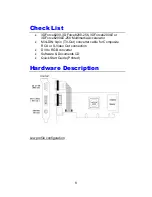
Page 8: ...00LE or 3DForce6200LE 256 Multimedia Accelerator Mini DIN 9 pin TV Out converter cable for Composite RCA or S Video Out connection DVI to RGB converter Software Documents CD Quick Start Guide Printed...

Page 9: ...6 1 X H 2 5 32M 16 x 2 DDR SDRAM 128MB 3DForce6200 256 82338B nVIDIA GeForce 6200 W 6 1 X H 2 5 32M 16 x 4 DDR SDRAM 256MB 3DForce6200LE 82338B nVIDIA GeForce 6200LE W 6 1 X H 2 5 16M 16 x 4 DDR SDRAM...

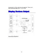
Page 10: ...Accessories for VGA cards are sold separately Please go to http Store anvshopper net for more details Display Devices Output Low profile configuration 10...

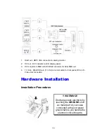
Page 11: ...er for Dual RGB out 4 TV Out Mini DIN 9 pin TV Out converter cable for Composite RCA or S Video Out connection Hardware Installation Installation Procedures WARNING Discharge static electricity by tou...

Page 12: ...edge connector on the adapter directly above the expansion slot connector on the motherboard Then press the adapter into place completely Use the remaining screw you removed to secure the adapter ret...

Page 13: ...hardware and places appropriate display driver from its system folder automatically it doesn t matter if you have added a new driver or changed the existing one To maximize the video board acceleratio...

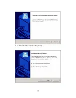
Page 14: ...2 Microsoft InstallShield Wizard has start loading its setup process please wait until it has completed 3 Click on Next to continue the process 14...

Page 15: ...e after Windows boots up Windows 2000 Driver Installation InstallShield Program Microsoft Windows 2000 detects this new hardware and places appropriate display driver from its system folder automatica...

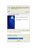
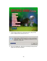
Page 16: ...orun feature brings up the Welcome Screen and you may point to Display Driver and then press on it 2 Microsoft InstallShield Wizard has start loading its setup process please wait until it has complet...

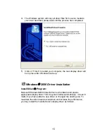
Page 17: ...3 Click on Next to continue the process 17...

Page 18: ...r or production developer To center the display with normal type mode 3 and to reduce decrease the refresh rate with the monitor s specification Q What kind monitors can display 800x600 modes or highe...

Page 19: ...d on again If the problem occurring in windows make sure that you have loaded that proper video driver and that the driver is compatible with the monitor being used Try re configuring your application...

Page 20: ...values for edges color and texture Q4 Why does a 3D graphics chip need to have both a rendering engine and a setup engine Answer Any 3D application a game VRML or modeling package can benefit from 3D...

Page 21: ...tion techniques As stated above SW 3D can achieve credible results with today s software optimized applications but the rising popularity of good 3D hardware at the consumer price level is inexorably...

Page 22: ...r cable requires a D shaped 9 pin female connector and a D shaped 15 pin male connector 9 to 15 Pin Conversion Table 9 PIN SIGNALS PIN NO 15 PIN SIGNALS PIN NO Red 1 Red 1 Green 2 Green 2 Blue 3 Blue...

Page 23: ...g Detect 17 TMDS Data 0 18 TMDS Data 0 19 TMDS Data 0 Shield 20 No Connection 21 No Connection 22 TMDS Clock Shield 23 TMDS Clock 24 TMDS Clock Technical Support In the event you have a technical prob...

Page 24: ...om Website www jaton com How to Obtain Warranty Service In the worldwide contact www jaton com In United States contact Jaton Corporation Service Center 556 S Milpitas Blvd Milpitas CA 95035 408 934 9...

Page 25: ...his device must accept any interference received including interference that may cause undesired operation SHIELD INTERFERENCE CABLE S MUST BE USED ACCORDING TO FCC 15 27 CAUTION Changes or modificati...

Page 26: ...sideration by Manufacturer occurs TRADEMARK AND COPYRIGHT This product incorporates copyright protection technology that is protected by U S patents and other intellectual property rights Use of this...

Page 27: ...place the defective products in the manner and for the period provided above Manufacturer shall not have any other obligation with respect to the Products or any part thereof whether based on contract...

Page 28: ...r 2 All returned checks will be charged a 20 00 fee by Manufacturer 3 All repair and replacement services allow 4 6 weeks from the date of receiving by Manufacturer 4 All products without warranties r...

Page 29: ...cts where compatibility issue are more likely to surface If you are unsure about installation for a new product contact your dealer s service department We believe it is important for you to know and...

Page 30: ...ice Use Only XXXX XX XXXXXX 00 0 xxxx xxxx XXXXX XXX XX S N A008000015 Product Label and Manufactured Date Code Serial Number ten or eleven digit code the serial number consists of the following parts...

Reviews: