3
GENERAL INSTALLATION INSTRUCTIONS
-
Install the boiler in an upright position on an incombustible surface in a dry boiler room.
-
Observe sufficient installation and maintenance space around the boiler.
-
Boiler connections to the network are done so that the piping is not strained.
-
Install necessary lock valves in the network for maintenance purposes.
-
During the network pressure test the boiler pressure must not exceed 1,5 bar.
-
After filling, the pipe connections and sealing are carefully checked to avoid damage to the
boiler and electric appliances from a possible leak.
-
The free combustion air opening, that is lead to the boiler room, should be at least the size
of the chimney aperture (150 mm x 150 mm).
-
The boiler is connected to the chimney with the chimney extension liner (standard
equipment). Joints must be carefully compressed with mineral wool, fibre glass braid or
equivalent to avoid the weakening of traction.
-
The distance between the boiler and the duct can be up to several metres. In that case the
connecting pipe should be in a horizontal or rather ascending position and the cross-section
must conform to chimney recommendations. The pipe should be isolated and the joints
sealed. Possibility to sweep the chimney should also be ensured.
INSTALLATION
Expansion system
Coated expansion container system
device) 1.5 bar safety valve whose blasting output should correspond to the amount of (water)
The safety valve is installed unclamped to the boiler’s boiling aggregate. The valve’s exhaust
pipe should not be reduced from it’s nominal size and it should be directed thus, that the
discharged vapor does not damage people or property.
The active volume of the coated expansion boiler should be at least 5% of the facility’s total
water quantity. In practice it should be dimensioned according to at least 7%.
Open expansion container system
On top of the boiler an unlocked sleeve pipe should be led to the expansion container. The
overflow pipe should be mounted descending. The vapor discharge pipe should be
continuously ascending and it’s pate directed thus, that it does not damage people or
property.
valve is mounted between the cold and hot water aggregates.
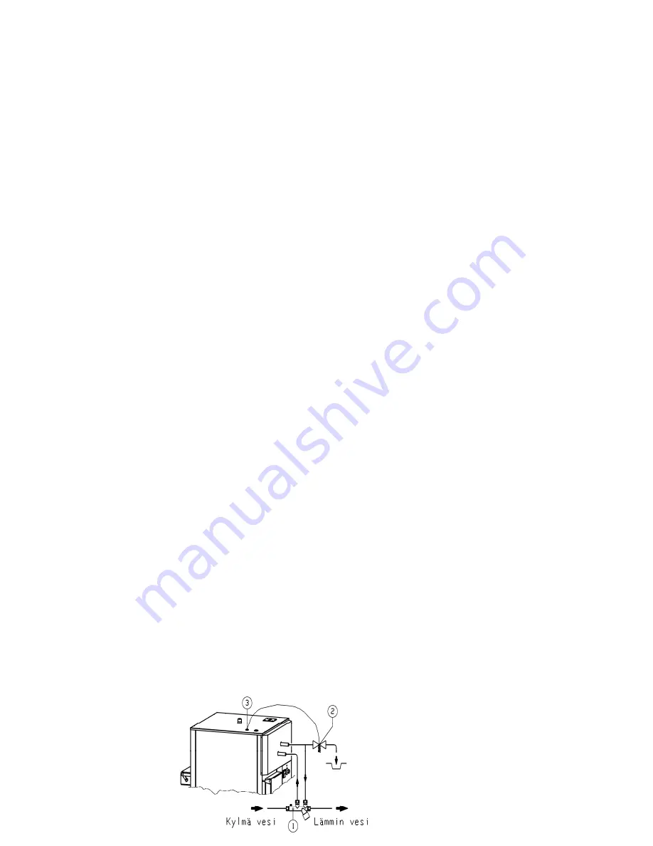
A boiling prevention valve must be connected to the hot water coil to block overheating when
wood is being burnt. Valve connection guidelines are shown in figure 2.
Figure 2. Connecting the boiling prevention valve (e.g. Jäspi-TSK) to the driving water coil.
1. Valve group
2. Boiling prevention valve
3. Sensor
vapor that is produced at maximum output
. Use of two safety valves is recommended.
a closing valve, a backlash valve and a 10 bar safety valve. The hot water thermostatic mixing
The cold water pipe connected to the DHW coil must equipped be with a valve group, including
Domestic hot water system (DHW)
On top of the boiler in the boiling connection there must be a reliable (without a clamping
container’s minimum volume must be 7% of the facility’s total water quantity. The container’s
WWW.JASPI.UK


