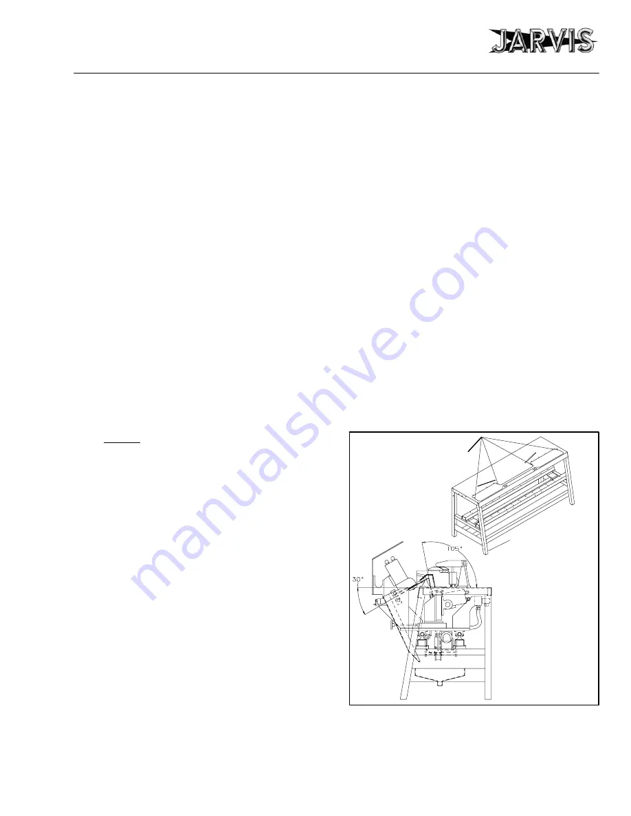
preliminary adjustments
Model NBS--1
page 27 of 32
6
JARVIS
6207019:
®
PRODUCTS CORPORATION
33 ANDERSON ROAD, MIDDLETOWN, CONNECTICUT 06457-4926
UNITED STATES OF AMERICA E--MAIL.
TEL. 860-347-7271 FAX. 860-347-6978 WWW.
jarvisproducts.com
1.5 Flow control (item 15, figure G, page 10) should
be set full counter clockwise for maximum car-
riage speed.
2 Bleed the carriage motor:
2.1 Remove hydraulic carriage motor (item 5, figure
D, page 7):
2.1.1 Remove screws (item 7, figure D, page 5) that
secure hydraulic carriage motor (item 5, fig-
ure D, page 5) to motor flanged housing (item
3, figure D, page 5). Separate motor (carriage)
from motor flanged housing.
2.1.2 Run motor in one direction for several minutes
to remove any excess air.
3 Adjust left and right side locating brackets (items 38
and 39, figure E, page 8).
4 Adjust limit switch wands (item 50, figure E, page 8)
to set desired carriage travel.
5 Adjust clamp assembly:
Note: Clamp assembly can be mounted on either side of
machine. Refer to figure C, page 6 for referenced items.
5.1 Disconnect air hoses (item 4) from fittings (item
41).
5.2 Remove screws (item 31).
5.3 Move clamp and valve to other side of table.
5.4 Loosely re--install screws (item 31).
5.5 Adjust positions of clamp lever (item 27), jaw
tooth(s) (item 33) and rotating couplings (item
29).
If these items are properly adjusted, meat
will be held tightly while cutting and saw blades
will not bind.
5.6 Tighten all screws that were loosened to make ad-
justments.
5.7 Set air pressure to 50 psi on air regulator (item 17).
6 Install blades.
Refer to maintenance section 4.
7 Align blade tips with blade setting instrument (part
number 3025018).
Refer to figure H, page 10):
Note: Carriage assembly must be moved to either the left
or right side guard (item 6 or 40, figure E, page 8), oppo-
site the clamp assembly to perform blade tip alignment
procedure.
7.1 Unlatch adjustable draw latch (item 8, figure E,
page 8).
7.2 Lift either left or right side tunnel (item 20 or 36,
figure E, page 8).
7.3 Loosen screws (item 2 figure F, page 9) to rotate
the horizontal and vertical blade motor and gear-
box assemblies until the desired blade angles are
achieved. After alignment is completed, tighten
screws (item 2, figure F, page 9).
7.4 Place blade setting instrument on blade alignment
tabs located on frame and table (item 51, figure E,
page 8).
Refer to figure 10, page 27.
7.5 Loosen knurled head screws (item 3, figure H,
page 10) and slide vertical gage (item 4, figure H,
page 10) and horizontal gage (item 5, figure H,
page 10) to desired setting.
7.6 Loosen thumb screws (items 24 and 28, figure I,
page 11) on slide before turning any knobs on ma-
chine.
7.7 Adjust one blade (item 24, figure F, page 9) by
turning knob (item 17, figure I, page 11) until
blade edge touches tip of horizontal gage (item 5,
figure H, page 10).
7.8 Slide blade setting instrument to the next blade.
7.9 Adjust blade edge until it touches tip of horizontal
gage (item 5, figure H, page 10).
7.10 When adjustment is completed, tighten thumb
screws (items 24 and 28, figure I, page 11). Re-
move blade setting instrument from NBS--1.
Figure 10
Frame and Table
Blade alignment
tabs used to locate
blade setting
instrument.
Approximate
blade angles.


