8
Replacing electronic components
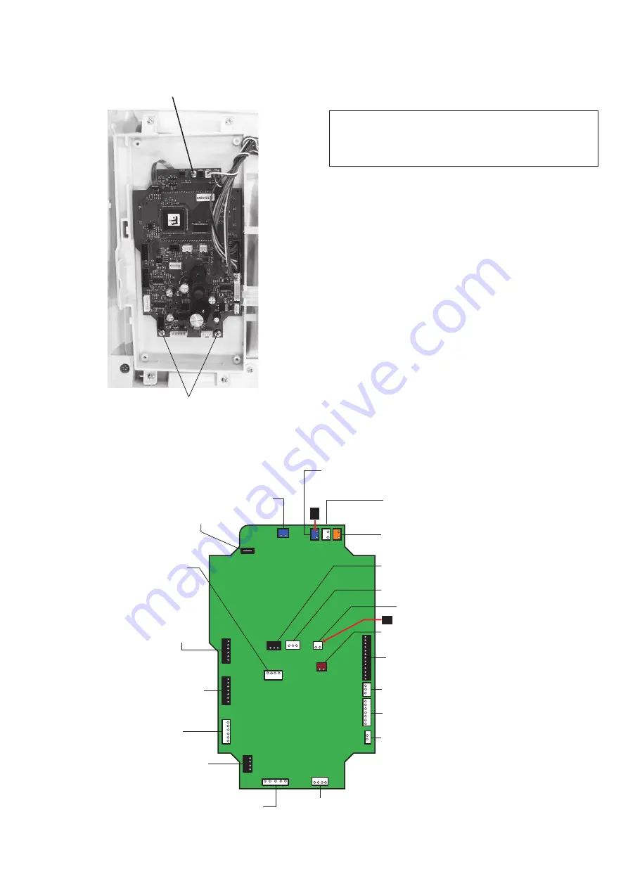
Printed circuit board A
NOTE:
Do not disconnect connectors by pulling on cord.
To disconnect the connectors, grasp the connector,
not the cord.
To remove:
1. Remove the front cover (refer to page 5).
2. Disconnect the connectors from the printed circuit
board A.
3. Remove the 3 setscrews and printed circuit board A.
To attach:
Follow the above procedure in reverse.
Refer to the board A schematic for locating the
connectors on the printed circuit board A.
After replacing the printed circuit board A, adjust the
following items:
• Knee Lifter (refer to page 37)
• Presser bar height (refer to page 29)
• Embroidery foot height (refer to page 35)
Board A schematic
Setscrew
Setscrew
Slide volume
Printed circuit board L1
(Underside of the arm)
Printed circuit board L2 (Underside of the function buttons)
* Plug the black connector
Touch panel
Bobbin winder
switch
Presser foot and
External thread cutter switch
Printed circuit board L2 (Face cover lamp)
BH sensor
Feed motor
Thread cutter motor
Solenoid 1
Thread tension release
Phase sensor
Printed circuit
board F
Zigzag stepping motor
DC motor
Program
Needle plate sensor switch
Drop feed switch
Foot control
* Plug the black connector
Power switch


