Page 20
Section 4. System Startup
4.1
Handheld Remote Programming
4.1.1. Basic Programming Menu
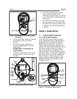
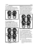
To set a particular piece of equipment to turn on
and off at predetermined times, highlight MENU
and press SELECT (see Figure 23). Highlight
PROGRAM and press SELECT. Use the UP or
DOWN buttons to highlight the equipment (for
example, Filter Pump) then press SELECT. Follow
the on-screen prompts. Use the UP or DOWN
buttons to pick each number, starting with ON
hours, press SE LECT to enter and move on to the
next item to change, including picking what day(s)
the program will run. If you make a mistake, use
the BACK button to return to a number. If the
program is already en tered, highlight CHANGE
PROGRAM and step through to the entry that
should be cor rect ed.
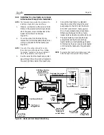
3. Use the UP and DOWN buttons to highlight
the desired RF channel. Then press
SELECT.
4. When the RF channel is selected, the
following message appears on the PDA
display screen:
Set slide switch on J-Box PCB to the
LEARN MODE.
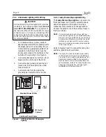
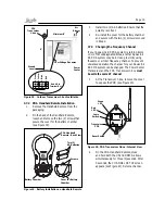
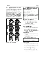
5. At the PCB in the Transceiver J-box, slide
the Learn Switch to LEARN (ON). See
Figure 22.
ÍÛÌ ÎÚ ÝØßÒÒÛ Ô
Î Ú ÝØßÒÒÛ Ôæ
ï
Ë-» ßÎÎÑÉ ÕÛÇÍ
¬± -»¬ ¬¸»
ÎÚ ÝØßÒÒÛÔò
Ю»-- ÍÛÔÛÝÌ ¬±
½±²¬·²«»ò
ï
î
-»´»½¬
¾¿½µ
ÐÜß
UP
Button
DOWN
Button
SELECT Button
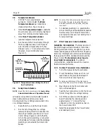
Figure 21. PDA Handheld Remote Channel Setup
and Buttons
ï
î
-»´»½¬
¾¿½µ
ÐÜß
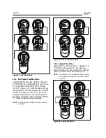
Figure 23. PDA Handheld Remote Buttons
BACK
Button
UP
Button
DOWN
Button
SELECT
Button
HOT KEY 1
HOT KEY 2
Power ON/OFF
Button
6. On the PDA Handheld Remote display
screen, a prompt will appear with
instructions to slide the J-box Learn Switch
out of LEARN (OFF) and to press the J-box
Reset Switch.
7. At the PCB in the Transceiver J-box, slide
the Learn Switch out of LEARN and press
the Reset Switch. The Red and Green LEDs
on the J-box will blink simultaneously (see
Figure 22).
Figure 22. Tranceiver J-box PCB Learn Switch
Óß×Ò ÝÑÒÒÛÝÌÑÎ
ÎÛÍÛÌ
Üî
Üí
Ô
Û
ß
Î
Ò
Ñ
Ú
Ú
Ñ
Ò
Ô
Û
ß
Î
Ò
Ñ
Ú
Ú
Ñ
Ò
Transceiver
PCB
Reset Switch
Learn
Switch
Shown
in Learn
Mode
- Switch
Position
On.
Green
LED
Red
LED
Summary of Contents for RS-P4
Page 2: ......
Page 28: ...Page 28 Section 6 Power Center Wiring Diagram...
Page 33: ...Page 33 NOTES...
Page 34: ...Page 34 NOTES...
Page 35: ......


