Page 19
Óß×Ò ÝÑÒÒÛÝÌÑ Î
ÎÛÍÛÌ
Üî
Üí
Ô
Û
ß
Î
Ò
Ñ
Ú
Ú
Ñ
Ò
3.7.2 PDA Handheld Remote Installation
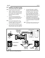
1. Remove the Handheld Remote from the
packaging.
2. On the back of the Handheld Remote,
loosen and remove the two (2) screws that
secure the cover for the battery chamber
(see Figure 19).
3. Install two (2) AA batteries. Ensure that the
polarity is correct.
4. Re-install the cover for the battery chamber
and secure with the two (2) screws removed
in Step 2.
3.7.3 Changing the Frequency Channel
If your AquaLink RS PDA system is turning items
on or off at undesignated times, another AquaLink
RS PDA system may be in close proximity using
the same or similar frequency channel. To prevent
unwanted operation the channel for your AquaLink
RS PDA system can be changed. The Power Center
Trans ceiv er and the PDA Transceiver J-box
must
be set to the same RF channel
.
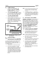
1. At the Transceiver J-box, remove the cover
to expose the PCB (see Figure 20).
Figure 20. PDA Transceiver J-Box - Internal View
Transceiver
PCB
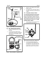
2. On the PDA Handheld Remote, press
and hold both the UP and DOWN arrows
simultaneously for three (3) seconds. After
3 seconds, the CHANNEL SETUP screen
appears (see Figure 21). Select a channel.
Low Voltage Raceway
Power
Center
Air
Blower
PDA
Trans ceiver
J-box
6'
Minimum 8'
Ground
Level
3
Y
el
lo
w
1
R
ed
2
B
la
c
k
4
G
re
en
Red 4-Pin
Terminal Bar
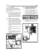
Figure 18. Outdoor Transceiver J-box Installation
Figure 19. Battery Installation on Handheld Remote
ËÓóíñÎêñßß
ËÓóíñÎêñßß
ÞßÌÌÛÎÇ
ïòëÊ ¨ î
íð íî ìð ï
ÓÑÜÛÔ ÒÑ èîêë
ÚÝÝ ×Üæ ÍèÚèîêÈ
כּ¼æ íÊ ÜÝ
PDA Handheld
Remote - Back View
Two (2)
AA Batteries
Battery Chamber
Cover for Battery
Chamber
Screws
Reset Switch
Learn
Switch
Green
LED
Red
LED
Summary of Contents for RS-P4
Page 2: ......
Page 28: ...Page 28 Section 6 Power Center Wiring Diagram...
Page 33: ...Page 33 NOTES...
Page 34: ...Page 34 NOTES...
Page 35: ......

