Page 9
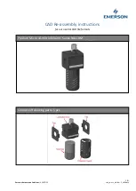
Figure 7 .
S weep E lb ow
N ote: Do not
ov ertighten.
LX i H e a t e r
CV F i l t e r
S H P
P u m p
S w e e p E l b o w
P / N S E A Q L1001
S w e e p E l b o w
P / N S E F L1002
7 ½ ”
M i n i m u m
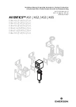
Figure 8 .
LX i Heater, C V Filter and S HP Pump S weep E lb ow I nstallation
C artridge Pool Filters - C L and C V S eries Filters
b.
Be sure there is a minimum distance of
7½ inches between the center of the pump
outlet port and the filter inlet bulkhead to
accommodate the sweep elbow(s). See
Figure 8 for recommended installation
configuration.
N O T E
T h e S H P p u m p sh
o w n i n F i g u r e 8 i s f o r r e f e r e n ce
o n l y . T h e Ja
n d y sw
e e p e l b o w a l so
w o r ks
w i t h t h e
M H P a n d P H P se
r i e s p u m p s.
NOTE Be sure to use 2" or 2½" schedule 40 PVC pipe.
c.
Clean the cut ends of the pipe and both ends
of the sweep elbow(s) with an appropriate
NSF
®
approved All Purpose cleaner/primer.
Glue the sweep elbow(s) onto the cut pipe
ends using an appropriate All Purpose NSF
®
approved adhesive/glue.
NOTE: Jandy recommends Weld-On 724 PVC to CPVC
Cement to glue Schedule 40 PVC.
d.
After the glue is cured, close the pressure
relief valve on top of the filter, start the
system and check for proper water flow.
6.
Make all plumbing connections in accordance
with local plumbing and building codes. Filter
connections are provided with an o-ring seal. To
avoid damage to the o-rings, use only a silicone
base lubricant on the o-rings.
Do not use pipe joint
compound, glue or solvent on inlet/outlet union
coupling nuts.
7.
Keep piping tight and free of leaks. Pump suction
line leaks may cause air to be entrapped in filter
tank or loss of prime at the pump. Pump discharge
line leaks may show up as dampness or jets of
water.
8. Support the inlet/outlet pipes independently to
prevent any undue strains on the filter valve.
9.
Connect the pipes using the unions supplied with
the filter.
Do not use Teflon tape or pipe dope on
any unions.
Assemble the unions dry and hand
tighten. See Figure 6.
10. If desired, the CV filter drain can be plumbed
using a Jandy universal union. The plumbing must
contain a ball valve as shown in Figure 6.
C A U T I O N
B e su
r e t h a t a l l p r o vi si o n s f o r w a st e w a t e r d i sp
o sa
l
m e e t l o ca
l , st a t e o r n a t i o n a l co
d e s. D u r i n g a n y
d r a i n i n g p r o ce
ss,
o n e h u n d r e d g a l l o n s ( 100 g a l s. )
o r m o r e o f p o o l w a t e r w i l l b e d i sch
a r g e d . CL a n d CV
( Ca r t r i d g e ) F i l t e r s a r e n o t su
b j e ct t o b a ckw
a sh
i n g . D o
n o t d i sch
a r g e w a t e r w h e r e i t w i l l ca
u se
f l o o d i n g o r
d a m a g e .