26
2.0 Service
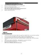
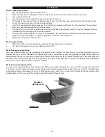
Replacing Brake Linings:
1.
Remove the brake shoe retract spring.
2.
Remove the shoe hold down assembly by holding the back of the pin with one hand and pushing against the spring and
twisting with a hold down spring tool until the cup is released.
3.
Remove both shoes together leaving the adjuster assembly and spring intact.
4.
Clean the backing plate and lever arm.
5.
Inspect magnet arm for any loose or worn parts.
6.
Replace springs that are broken, bent, or weak.
7.
Apply a light film of lubricant to the anchor pin and shoe rest pads & backing plate areas that are in contact with the lever arm.
8.
Attach the adjuster screw and spring to the new brake shoes. The star wheel and adjuster must be
positioned as before.
9.
Install the new shoes on the backing plate and reinstall shoe retract spring.
After replacement of brake shoes and linings, the brake must be re-burnished to seat in the new components. This should be done by
applying the brakes 20 to 30 times from an initial speed of 40 m/h, slowing the vehicle to 20 m/h. Allow ample time for brakes to cool
between applications. This procedure allows the brake shoes to seat into the drum surface.
Brake Lubrication:
Before reassembling, apply a light film of lubrication or similar grease, or anti-seize compound on the brake anchor pin, the actuating
arm bushing and pin, and the areas of the backing plate that are in contact with the brake shoes and magnet lever arm. Apply a light
film of grease on the actuating block mounted on the actuating arm.
Troubleshooting:
Most electric brake malfunctions that cannot be corrected by either brake adjustments or synchronization adjustments can generally
be traced to electrical system failure. Mechanical causes are ordinarily obvious, bent or broken parts, worn out linings or magnets,
seized lever arms or shoes, scored drums, loose parts, etc. Voltmeter and ammeter are essential tools for proper troubleshooting of
electric brakes.
How to Measure Voltage:
System voltage is measured at the magnets. Connect the voltmeter to the two magnet lead wires at any brake. This may be accom-
plished by using a pin probe inserted through the insulation of the wires dropping down from the chassis or by cutting the wires.
The
engine of the towing vehicle should be running when checking the voltage (so that a low battery will not affect the readings).
Brake Magnet Inspection:
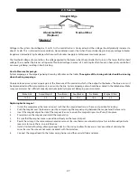
Your electric brakes are equipped with high quality electromagnets that are designed to provide the proper force and friction. Your
magnets should be inspected and replaced if worn unevenly or abnormally (Figure 2.7). Even if wear is normal as indicated by your
straightedge, the magnets should be replaced if any part of the magnet coil has become visible through the friction material facing
of magnet. It is also recommended that the drum armature surface be re-faced when replacing magnets. Magnets should also be
replaced in pairs - both sides of an axle.
Summary of Contents for 510-ST
Page 3: ...3...
Page 9: ...9 Decals 4 11 13 7 12 14 9 10 11 16 15 17...
Page 33: ...33...
Page 55: ...55...
Page 57: ...57 5 0 Parts Includes 6 Dia Clamp with M10 X 1 1 2 L Bolt 5 6 7 8 9...


