Page 19
1998-2006 Edition
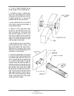
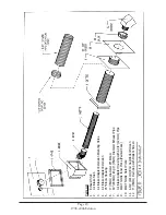
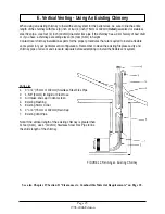
5. Apply a liberal bead of RTV silicone around the perimeter of the exhaust stub.
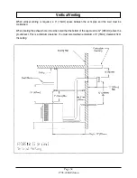
6. Slide the female end of the 3" (76mm) L-type vent pipe over the exhaust stub as far as it will go. Secure the pipe
in place using three #8 x 1” self drilling and tapping screws evenly spaced around the perimeter of the 3" (76mm) pipe.
7. Slide one part of the wall thimble over the far end of the 3" (76mm) pipe. Make sure that the round collar on the
wall thimble is towards the hole in the wall.
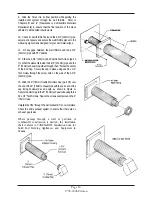
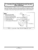
8. Carefully slide the stove into its final position while guiding the 3" (76mm) pipe through the 7" (178mm) hole in the
wall. Remember to maintain all the required clearances to the walls and any combustible objects adjacent to the stove.
Refer to Chapter III and IV of this manual.
9. Center the wall thimble part in the 7" (178mm) hole and secure to the wall using four screws appropriate for the
existing wall type.
10. Seal the gap between the wall thimble and the 3" (76mm) pipe using RTV silicone.
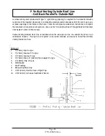
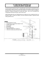
11. From the outside of the home, slide the outside part of the wall thimble over the end of the 3" (76mm) pipe. Secure
the wall thimble to the exterior siding of the house and seal the gap between the 3" (76mm) pipe and the wall thimble
with RTV silicone. Use the appropriate screw type for the type of siding on the house.
12. Apply a bead of RTV silicone to the end of the 3" (76mm) pipe.
13. Affix the exhaust termination cap to the end of the 3" (76mm) pipe and secure in place with three #8 x 1" self
drilling and tapping screws, spaced evenly around the perimeter of the 3" (76mm) pipe.
14. Use the same method to attach the 1-5/8" (41mm) air intake rigid tube or flexible hose to the air intake stub.
However, it is not necessary to use 3 screws to secure the air intake tube/hose to the air intake stub.
15. Use the appropriate elbows or other fittings to channel the air intake tube/hose to the location of the 1-3/4” (45mm)
hole in the wall. Trim the air intake tube approximately flush with the outside of the wall. Remember, installation of an
end cap with a rodent screen or louvers is required to prevent birds and/or rodents from entering the air intake tube.
16. Seal the gap between the air intake tube and the 1-3/4" (45mm) hole in the wall using an appropriate sealant
material for the existing wall type.
Summary of Contents for J1000B
Page 2: ......
Page 8: ...Page vi 1998 2006 Edition ...
Page 16: ...Page 8 1998 2006 Edition ...
Page 20: ...Page 12 1998 2006 Edition ...
Page 36: ...Page 28 1998 2006 Edition ...
Page 44: ...Page 36 1998 2006 Edition ...
Page 45: ...Page 37 1998 2006 Edition ...
Page 46: ...VIII 5 Jamestown Control Panel Page 38 1998 2006 Edition ...
Page 61: ...Page 53 1998 2006 Edition ...
Page 62: ...Page 54 1998 2006 Edition ...
Page 63: ...Page 55 1998 2006 Edition ...
Page 64: ...Page 56 1998 2006 Edition ...
Page 69: ...Page 61 1998 2006 Edition ...
Page 70: ...Page 62 1998 2006 Edition ...
Page 79: ...Appendix A 3 1998 2006 Edition ...
Page 80: ...Appendix A 4 1998 2006 Edition ...
Page 81: ...Appendix A 5 1998 2006 Edition ...
Page 82: ...Appendix A 6 1998 2006 Edition ...
Page 84: ...Appendix B 2 1998 2006 Edition ...
Page 87: ...APPENDIX E AUGER MOTOR BRACKET INSTALLATION Appendix E 1 1998 2006 Edition ...
Page 90: ...Appendix F 3 1998 2006 Edition ...
Page 93: ...APPENDIX H J1000 CROSSFLOW FAN Part 07EEG Appendix H 1 1998 2006 Edition ...
Page 94: ...APPENDIX I 1 EXHAUST BLOWER ASSEMBLY MODEL J1000 Appendix I 1 1998 2006 Edition ...


